CABLE ROUTING DIAGRAM
Frame and engine (left side view)
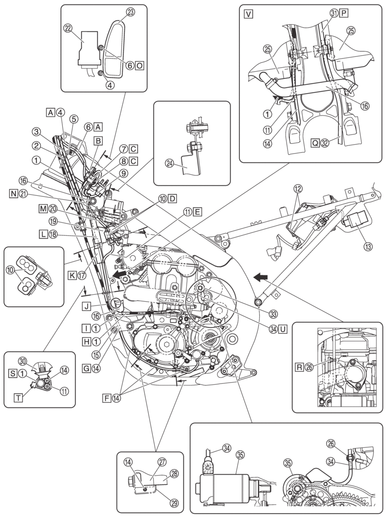
|
1. |
Clutch cable |
|
2. |
Throttle cable (return) |
|
3. |
Throttle cable (pull) |
|
4. |
Mode switch lead |
|
5. |
Cable holder |
|
6. |
Engine stop switch lead |
|
7. |
Mode switch coupler |
|
8. |
Engine stop switch coupler |
|
9. |
Intake air temperature sensor coupler |
|
10. |
Rectifier/regulator coupler |
|
11. |
Stator coil assembly lead |
|
12. |
Battery band |
|
13. |
CCU (Communication Control Unit) |
|
14. |
Gear position switch lead |
|
15. |
Lower engine bracket |
|
16. |
Radiator hose |
|
17. |
Gear position switch coupler |
|
18. |
Stator coil assembly coupler |
|
19. |
Tension arm |
|
20. |
Rectifier/regulator lead |
|
21. |
Wire harness |
|
22. |
Yamaha diagnostic tool coupler |
|
23. |
Tank rail |
|
24. |
Rectifier/regulator |
|
25. |
Radiator |
|
26. |
Clamp |
|
27. |
Crankcase cover |
|
28. |
Crankcase |
|
29. |
Clamp |
|
30. |
Frame |
|
31. |
Cylinder head breather hose |
|
32. |
Radiator breather hose |
|
33. |
Engine mounting bracket boss |
|
34. |
Starter motor lead |
|
35. |
Starter motor |
|
A. |
Pass the engine stop switch lead and the mode switch lead between the frame and the cable holder. Route engine stop switch lead and the mode switch lead above of the vehicle. Pass the mode switch lead above the engine stop switch lead. |
|
B. |
Insert the Yamaha diagnostic tool coupler into the connector, and fix it to the bracket. |
|
C. |
Fasten the engine stop switch coupler to the bracket of the inside. Fasten the mode switch coupler to the bracket of the outside. Route the mode switch lead under the bracket. |
|
D. |
Fasten the rectifier/regulator coupler to the bracket. Attach the coupler cover. |
|
E. |
Pass the stator coil assembly lead through rear side of the vehicle. No pinch is allowed between the radiator and the tension arm. |
|
F. |
Route the gear position switch lead along the crankcase without slack. |
|
G. |
Pass the gear position switch lead to the inside of the lower engine bracket (the side of the vehicle). |
|
H. |
Pass the clutch cable with no downward sag allowed. |
|
I. |
Bring the protector of the clutch cable into contact with the radiator hose, and pass it to the outside of the gear position switch lead and the stator coil assembly lead (the outside of the vehicle). |
|
J. |
No pinch is allowed the leads between the radiator and the tension arm. |
|
K. |
After connecting the gear position switch coupler, attach the coupler cover. |
|
L. |
After connecting the stator coil assembly coupler, attach the coupler cover. |
|
M. |
Pass the rectifier/regulator lead (wire harness side) to the inside of the tension arm (the side of the vehicle). |
|
N. |
Pass the main harness to the front of the radiator hose (the front of the vehicle), and to the inside of the throttle cable (the side of the vehicle). |
|
O. |
Pass the engine stop switch lead and mode switch lead between the Yamaha diagnostic tool coupler and the tank rail. |
|
P. |
Pass the cylinder head breather hose between the down tube and radiator, and front of the radiator under boss. |
|
Q. |
Route the radiator breather hose between the down tubes. |
|
R. |
Insert the clamp into the hole in the cylinder head. When doing so, the starter motor lead should not be twisted. |
|
S. |
Clamp the clutch cable at the front of the lead (the front of the vehicle). |
|
T. |
Insert the clamp into the hole in the frame. Cut off the excess end of the locking portion, and the locking portion should face toward the front of the vehicle. |
|
U. |
Route the starter motor lead through the inside of the engine mounting bracket boss and along the front side of the vehicle behind the engine mounting bracket boss. |
|
V. |
Diagram for routing the radiator hose, cylinder head breather hose, and radiator breather hose. |
Frame and engine (right side view)
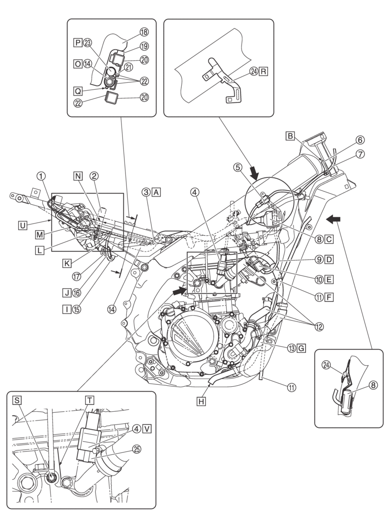
|
1. |
Negative battery lead |
|
2. |
Cross tube |
|
3. |
Starter motor lead |
|
4. |
Coolant temperature sensor coupler |
|
5. |
Start switch coupler |
|
6. |
Cable guide |
|
7. |
Start switch lead |
|
8. |
Joint coupler |
|
9. |
Throttle position sensor lead |
|
10. |
Throttle position sensor coupler |
|
11. |
Radiator breather hose |
|
12. |
Radiator hose |
|
13. |
Cylinder head breather hose |
|
14. |
Fuel hose |
|
15. |
Fuel pump coupler |
|
16. |
Fuel pump lead |
|
17. |
Diode |
|
18. |
Fuel tank |
|
19. |
Rubber damper |
|
20. |
Rear frame |
|
21. |
Starter motor lead |
|
22. |
Side cover |
|
23. |
Wire harness |
|
24. |
Bracket |
|
25. |
Holder |
|
A. |
Adjust any slack between the rear shock absorber and the clamp of the side cover. |
|
B. |
Make sure the cable guide has contact with the stamped location of the vehicle identification number, and install it. |
|
C. |
Insert the joint coupler into the plate and secure it. After securing it, put the cover over the joint coupler. The inserted portion of the coupler should be hidden with the cover. |
|
D. |
Pass the throttle position sensor lead through the outside of the cylinder head breather hose. |
|
E. |
After connecting the throttle position sensor coupler, attach the cover. |
|
F. |
The radiator breather hose should be routed in the following order and via each mentioned point.
|
|
G. |
Pass the cylinder head breather hose between the radiator hose and the engine bracket. |
|
H. |
Install the cylinder head breather hose so that the outlet faces downward. Align the outlet with the lower side of the down tube. |
|
I. |
After connecting the fuel pump coupler, attach the cover. |
|
J. |
Pass the fuel pump lead through the outside of the fuel hose. |
|
K. |
Pass the fuel hose through the front of the battery. |
|
L. |
Fasten the starter relay lead and starter motor lead with the plastic locking tie within the range of the cross tube width. Make sure that the locking portion of the plastic locking tie faces to the lower side of the vehicle and put it inside the rear frame without cutting off the end. |
|
M. |
Route the starter motor lead inside of the rear frame and along the rear fender. |
|
N. |
20 mm (0.7874 in) |
|
O. |
Fasten the fuel hose at the pink dot position using the plastic locking tie. |
|
P. |
Fasten the wire harness at the white tape position using the plastic locking tie. |
|
Q. |
Position the lock part of the plastic locking tie to downward of the vehicle. Cut the end of the plastic locking tie. |
|
R. |
Fasten the bracket to the tank rail (right) using the rivet. |
|
S. |
When installing the engine ground lead terminal, it can face either way. Make sure that the terminal does not contact the cylinder head bolt and that it faces to the rear beyond the cylinder ridge line. |
|
T. |
Cylinder head ridge line |
|
U. |
The routing order of leads not indicated does not matter. |
|
V. |
After the connection, attach the cover to the holder. |
Handlebar (front view)
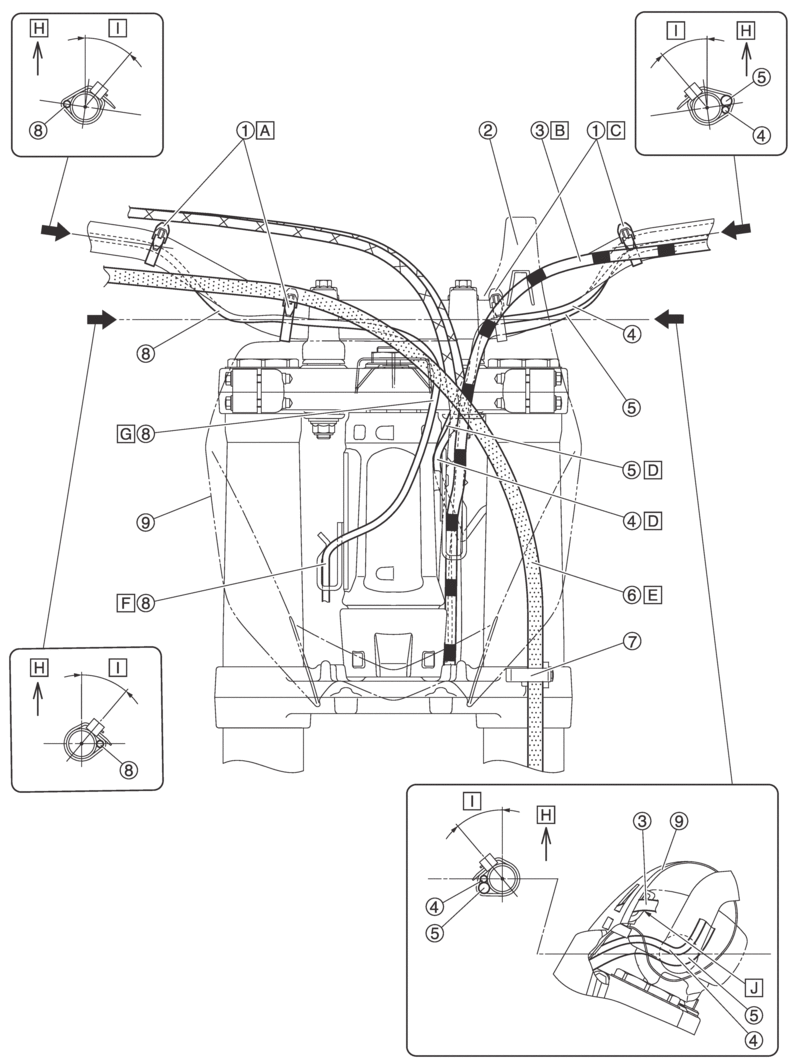
|
1. |
Plastic locking tie |
|
2. |
Number plate band |
|
3. |
Clutch cable |
|
4. |
Engine stop switch lead |
|
5. |
Mode switch lead |
|
6. |
Front brake hose |
|
7. |
Cable guide |
|
8. |
Start switch lead |
|
9. |
Number plate |
|
A. |
Fasten the start switch lead to the handlebar using the plastic locking tie. Do not cut the end of the plastic locking tie. |
|
B. |
Pass the clutch cable through the rear side of the number plate band. |
|
C. |
Fasten the engine stop switch lead and mode switch lead to the handlebar using the plastic locking tie. Do not cut the end of the plastic locking tie. |
|
D. |
Pass the engine stop switch lead and mode switch lead between the frame and the cable guide. |
|
E. |
Pass the front brake hose through the front side of the number plate. |
|
F. |
Pass the start switch lead between the frame and the cable guide. |
|
G. |
Pass the start switch lead through the left side of the number plate mounting bracket. |
|
H. |
Vertical direction of vehicle |
|
I. |
30–50° |
|
J. |
Pass the clutch cable through the guide of the number plate. |
Frame and engine (top view)
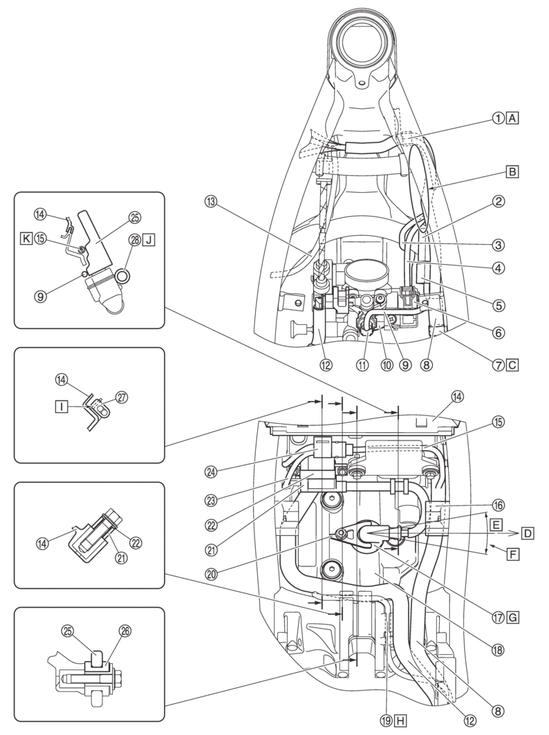
|
1. |
Clamp |
|
2. |
Diode |
|
3. |
Throttle position sensor lead |
|
4. |
Intake air pressure sensor lead |
|
5. |
Joint coupler |
|
6. |
Intake air pressure sensor coupler |
|
7. |
Clamp (wire harness) |
|
8. |
Wire harness |
|
9. |
Fuel injector lead |
|
10. |
Throttle body |
|
11. |
Fuel injector coupler |
|
12. |
Fuel hose |
|
13. |
Rectifier/regulator lead |
|
14. |
Air filter assembly |
|
15. |
Wire harness |
|
16. |
Fuel tank bracket |
|
17. |
Plug cap |
|
18. |
Cylinder head cover |
|
19. |
Starter motor lead |
|
20. |
Holder |
|
21. |
Ignition coil |
|
22. |
Side core |
|
23. |
Sub-lead wire |
|
24. |
Sub-lead wire coupler |
|
25. |
ECU (Engine Control Unit) |
|
26. |
Grommet |
|
27. |
Clamp |
|
28. |
High tension cord |
|
A. |
Fasten the main harness and start switch lead by the clamp, and insert the clamp projection into the hole in the sheet metal of the radiator. The direction of the clamp lock portion does not matter. It is allowed to run the leads near the radiator cap on the inside. |
|
B. |
No pinch is allowed the leads between the tank rail and the air filter joint. |
|
C. |
Insert the projection of the main harness into the hole in the frame. |
|
D. |
Right side of the vehicle. |
|
E. |
±10° |
|
F. |
Install the plug cap so it faces to the right side of the vehicle. |
|
G. |
Push the spark plug cap home, where there shall be no gap between it and the cylinder head cover. |
|
H. |
Fasten the starter motor lead along the locating damper. |
|
I. |
Insert the clamp into the rib so that it contacts the rib. |
|
J. |
It does not matter if the high tension cord and grommet do not contact the ECU. |
|
K. |
Pass the wire harness between the ECU and air filter assembly. |
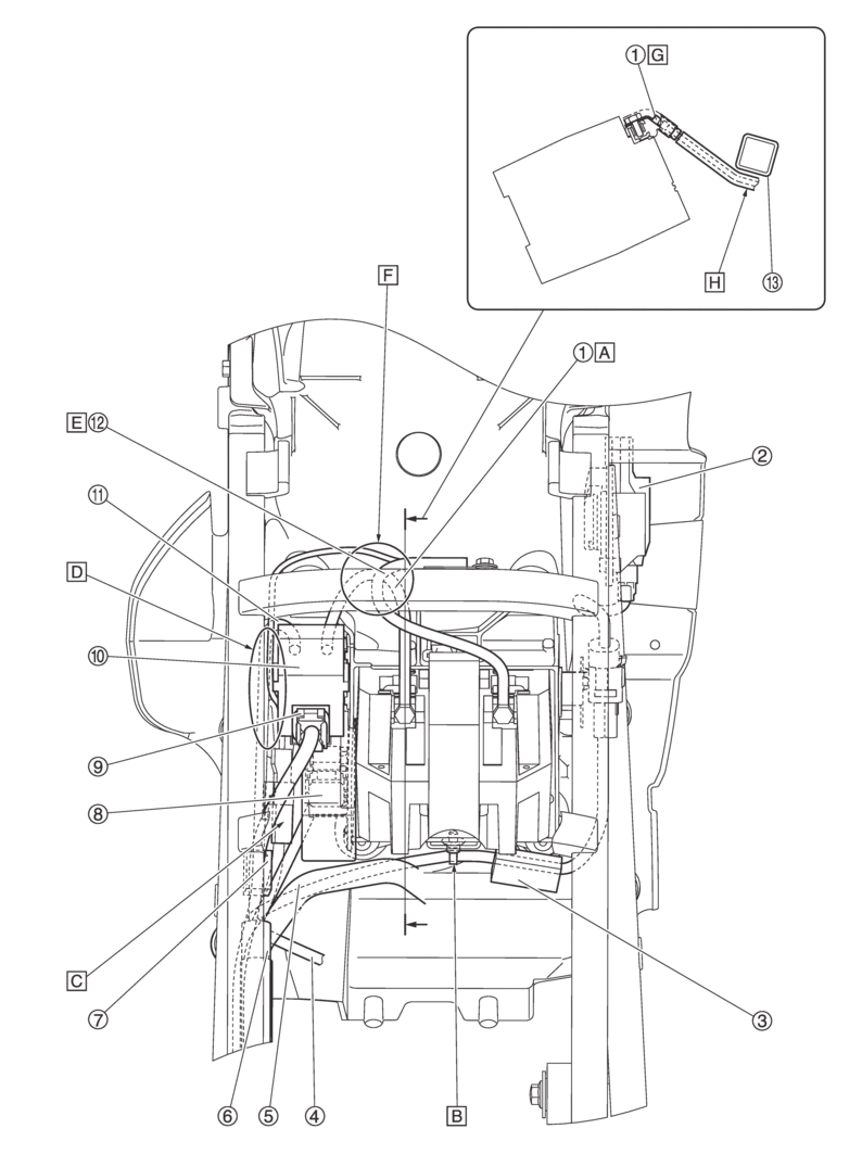
Frame and battery (top view)
|
1. |
Positive battery lead |
|
2. |
CCU (Communication Control Unit) |
|
3. |
Diode |
|
4. |
Fuel pump lead |
|
5. |
Fuel hose |
|
6. |
Wire harness |
|
7. |
Joint coupler |
|
8. |
Main relay |
|
9. |
Starter relay coupler |
|
10. |
Starter relay |
|
11. |
Starter motor lead |
|
12. |
Negative battery lead |
|
13. |
Cross member |
|
A. |
Connect the positive battery lead and starter relay terminal. |
|
B. |
Install the clamp (wire harness) to the hole of the battery bracket. |
|
C. |
After connecting the negative battery coupler, position to the right side of the starter relay. |
|
D. |
The position of the starter motor lead and negative battery lead does not matter. |
|
E. |
Pass the negative battery lead through lower side of the cross member. |
|
F. |
The position of the negative battery lead in relation to the battery side and coupler side and the corresponding position of the positive battery lead do not matter. |
|
G. |
After connecting the positive battery lead in the direction shown in the illustration, put the cover over it. |
|
H. |
Pass the positive battery lead through the lower side of the cross member. |
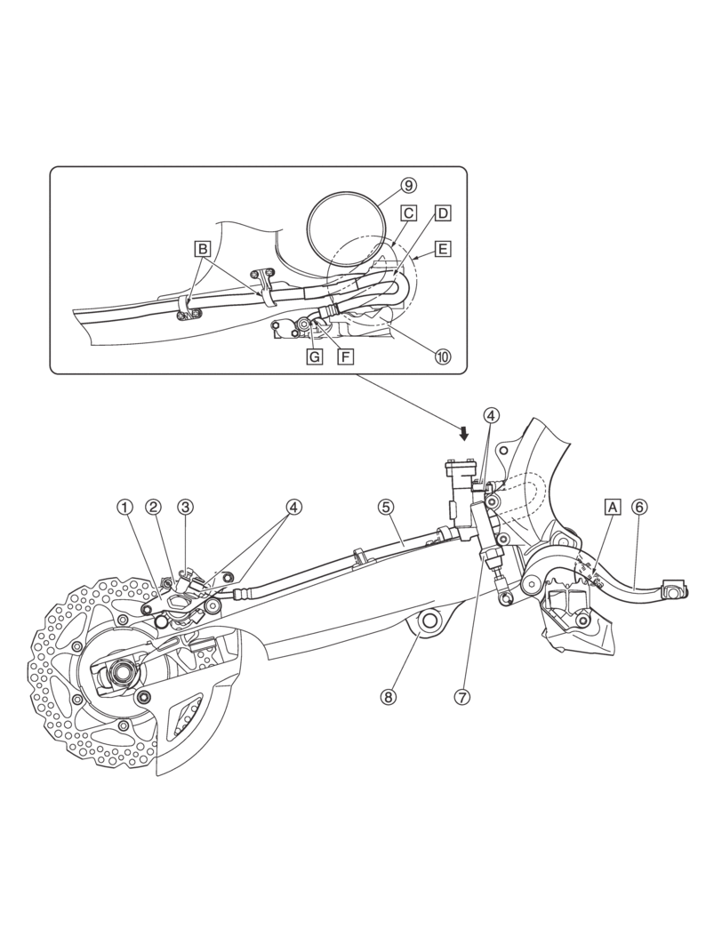
Rear brake (right side view)
|
1. |
Protector |
|
2. |
Rear brake caliper |
|
3. |
Bleed screw |
|
4. |
Gasket |
|
5. |
Rear brake hose |
|
6. |
Brake pedal |
|
7. |
Rear brake master cylinder assembly |
|
8. |
Swingarm |
|
9. |
Spring |
|
10. |
Frame |
|
A. |
It does not matter whether the spring is installed upward or downward. |
|
B. |
Pass the rear brake hose into the rear brake hose holders. |
|
C. |
Route the rear brake hose so that it is not bent as shown by the double-dash line. |
|
D. |
Route the rear brake hose and spring so that they do not interfere with each other. |
|
E. |
Make sure that the rear brake hose is not excessively twisted. |
|
F. |
Make sure that the metal part of the rear brake hose contacts the stopper of the rear brake master cylinder. |
|
G. |
Install the rear brake hose so that the bended portion of the metal part of the rear brake hose faces as shown in the illustration. |

