INSTRUMENT AND CONTROL FUNCTIONS
WARNING LIGHTS
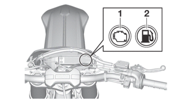
|
1. |
Engine trouble warning light “ |
|
2. |
Fuel level warning light “ |
Engine trouble warning light “ ”
”
This warning light comes on or flashes if a problem is detected in the electrical circuit monitoring the engine. If this occurs, have a Yamaha dealer check the vehicle.
The electrical circuit of the warning light can be checked by pushing the start switch. The warning light should come on for a few seconds, and then go off.
If the warning light does not come on initially when the start switch is pushed, or if the warning light remains on, have a Yamaha dealer check the electrical circuit.
Fuel level warning light “ ”
”
This warning light comes on when the fuel level drops below approximately 2.1 L (0.55 US gal, 0.46 Imp.gal). When this occurs, refuel as soon as possible.
The electrical circuit of the warning light can be checked by pushing the start switch. The warning light should come on for a few seconds, and then go off.
If the warning light does not come on initially when the start switch is pushed, or if the warning light remains on, have a Yamaha dealer check the electrical circuit.
ENGINE STOP SWITCH
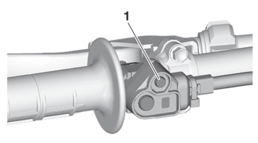
The engine stop switch “1” is located on the left handlebar. Continue pushing the engine stop switch till the engine comes to a stop.
START SWITCH
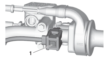
The start switch “1” is located on the right handlebar. Push this switch to crank the engine with the starter.
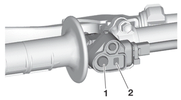
LAP TIME RECORD MODE
Lap time records can be measured by activating from the Power Tuner app.
When the mode switch “1” is pressed, the indicator light “2” will blink in blue and the measurement will start.
|
DRIVE MODE
Push the mode switch “1” to change between drive mode 1 and drive mode 2.
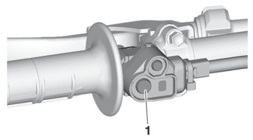
To change the drive mode
1.Shift to neutral.
2.Start the engine.
3.Push the mode switch “1”.
Mode 1
All-around good engine power and throttle response.
Mode 2
Milder throttle response for riding technical sections.
|

SHIFT PEDAL
The shift pedal “1” has adopted a method of 1 down & 5 ups (press-down & kick-ups).
Press it down for N (neutral) to 1st, and kick it up for 2nd to 6th.

Recommended shift points
The recommended shift points during acceleration and deceleration are shown in the table below.
|
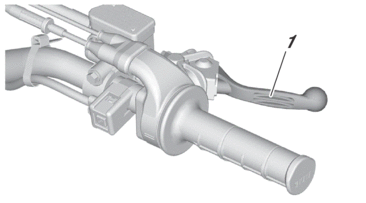
FRONT BRAKE LEVER
The front brake lever “1” is located on the right handlebar. Pull it toward the handlebar to activate the front brake.
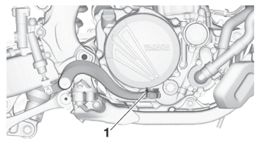
REAR BRAKE PEDAL
The rear brake pedal “1” is in the right of the chassis. Press down on the brake pedal to activate the rear brake.
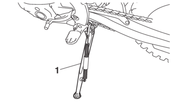
SIDESTAND
This sidestand “1” is used to support only the machine when standing.
|
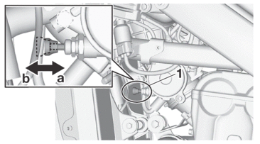
STARTER KNOB
Starting a cold engine requires a larger amount of intake air, which is supplied by the starter knob “1”.
Pushing the knob toward “a” turns ON the starter, resulting in a larger angle of throttle valve.
|
|
FUEL TANK CAP
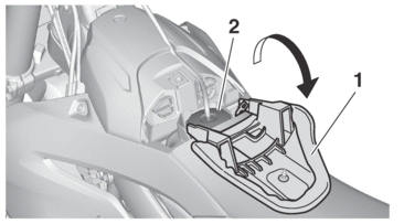
Fuel tank cap is located under the sub-seat.
1.Loosen:
-
Quick fastener “1”
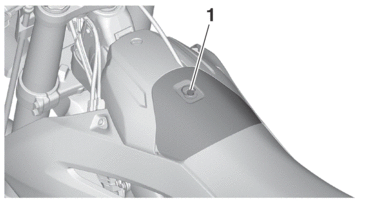
2.Remove the sub-seat “1” to open the fuel tank cap “2”.
|
