CLUTCH

|
Removing the clutch  |
|||
|---|---|---|---|
|
Order |
Job/Parts to remove |
Q’ty |
Remarks |
|
|
Engine oil |
|
Drain. Refer to CHANGING THE ENGINE OIL. |
|
1 |
Clutch cable |
1 |
Disconnect. |
|
2 |
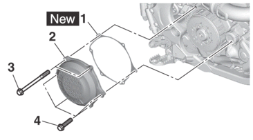
Clutch cover |
1 |
|
|
3 |
Gasket |
1 |
|
|
4 |
Pressure plate 1 |
1 |
|
|
5 |
Clutch spring |
1 |
|
|
6 |
Spring retainer |
1 |
|
|
7 |
Pressure plate 2 |
1 |
|
|
8 |
Circlip |
1 |
|
|
9 |
Bearing |
1 |
|
|
10 |
Push rod 1 |
1 |
|
|
11 |
Ball |
1 |
|
|
Removing the clutch  |
|||
|---|---|---|---|
|
Order |
Job/Parts to remove |
Q’ty |
Remarks |
|
12 |
Clutch plate 2 |
2 |
[Thickness: 1.0 mm (0.04 in)] |
|
13 |
Friction plate 2 |
4 |
Blue paint on the outer circumference of the pawls. |
|
14 |
Clutch plate 1 |
7 |
[Thickness: 1.4 mm (0.06 in)] |
|
15 |
Friction plate 1 |
4 |
|
|
16 |
Collar |
6 |
|
|
17 |
Washer |
1 |
|
|
18 |
Sleeve |
1 |
|
|
19 |
Absorber |
6 |
|
|
20 |
Clutch boss |
1 |
|
|
21 |
Washer |
1 |
|
|
22 |
Primary driven gear |
1 |
|
|
23 |
Collar |
1 |
|
|
24 |
Idle gear |
1 |
|
|
25 |
Washer |
1 |
|
|
Removing the crankcase cover (right)  |
|||
|---|---|---|---|
|
Order |
Job/Parts to remove |
Q’ty |
Remarks |
|
|
Right engine guard |
|
Refer to ENGINE REMOVAL. |
|
|
Engine oil |
|
Drain. Refer to CHANGING THE ENGINE OIL. |
|
|
Coolant |
|
Drain. Refer to CHANGING THE COOLANT. |
|
|
Brake pedal |
|
Refer to ENGINE REMOVAL. |
|
|
Clutch cover |
|
Refer to CLUTCH. |
|
1 |
Oil filter element cover |
1 |
|
|
2 |
Oil filter element |
1 |
|
|
3 |
Oil filler cap |
1 |
|
|
4 |
Crankcase cover (right) |
1 |
|
|
5 |
Gasket |
1 |
|
|
6 |
Dowel pin |
2 |
|
|
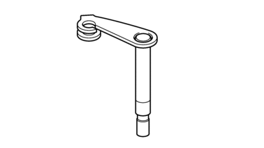
Removing the clutch release  |
|||
|---|---|---|---|
|
Order |
Job/Parts to remove |
Q’ty |
Remarks |
|
|
Drive sprocket cover |
|
Refer to CHAIN DRIVE. |
|
1 |
Push lever shaft |
1 |
|
|
2 |
Clutch release |
1 |
|
|
3 |
Oil seal |
1 |
|
|
4 |
Bearing |
2 |
|
|
5 |
Push rod 2 |
1 |
|
|
6 |
Oil seal |
1 |
|
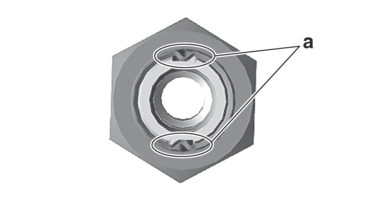
REMOVING THE CLUTCH
1.Straighten the clutch boss nut rib “a”.
2.Remove:
-
Clutch boss nut “1”
-
Washer “2”
-
Sleeve “3”
-
Absorber
-
Clutch boss
|
|

CHECKING THE FRICTION PLATES
1.Check:
-
Friction plate
Damage/wear → Replace the friction plates as a set.
2.Measure:
-
Friction plate thickness
Out of specification → Replace the friction plates as a set.
|
|

CHECKING THE CLUTCH PLATES
1.Check:
-
Clutch plate
Damage → Replace the clutch plates as a set.
2.Measure:
-
Clutch plate warpage
(with a surface plate and thickness gauge)
Out of specification → Replace the clutch plates as a set.
|
|
CHECKING THE CLUTCH SPRING
1.Check:
-
Pressure plate
Damage → Replace.
2.Check:
-
Spring retainer
Damage → Replace.
3.Check:
-
Clutch spring
Damage → Replace the clutch spring.
4.Measure:
-
Clutch spring free height
Out of specification → Replace the clutch spring.
|
CHECKING THE COLLAR
1.Check:
-
Collar “1”
Damage/pitting/wear → Replace the collars as a set.

-
Pitting on the collar will cause erratic clutch operation.
CHECKING THE PRESSURE PLATE
1.Check:
-
Pressure plate
Crack/damage → Replace.
CHECKING THE PUSH LEVER SHAFT
1.Check:
-
Push lever shaft
Wear/damage → Replace.
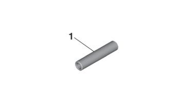
CHECKING THE PUSH ROD
1.Check:
-
Push rod 1 “1”
-
Bearing “2”
-
Ball “3”
-
Push rod 2 “4”
Cracks/damage/wear → Replace.
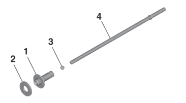
2.Measure:
-
Push rod 2 bending limit
Out of specification → Replace.
|
CHECKING THE PRIMARY DRIVE GEAR
1.Check:
-
Primary drive gear
Damage/wear → Replace the primary drive and primary driven gears as a set.
Excessive noise during operation → Replace the primary drive and primary driven gears as a set.
2.Check:
-
Primary-drive-gear-to-primary-driven-gear free play
Free play exists → Replace the primary drive and primary driven gears as a set.
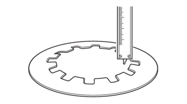
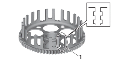
CHECKING THE PRIMARY DRIVEN GEAR
1.Check:
-
Primary driven gear
Damage/wear → Replace the primary drive and primary driven gears as a set.
Excessive noise during operation → Replace the primary drive and primary driven gears as a set.
2.Check:
-
Primary driven gear dogs “1”
Damage/pitting/wear → Deburr the primary driven gear dogs or replace the primary driven gear.
|
ASSEMBLING THE CLUTCH RELEASE
1.Install:
-
Bearing “1”

-
Oil seal “2”
|
|
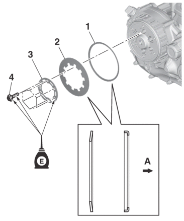
INSTALLING THE CLUTCH RELEASE
1.Install:
-
Oil seal “1”
|
2.Install:
-
Push rod 2 “1”
-
Washer “2”
-
O-ring “3”
-
Clutch release “4”
|

|

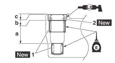
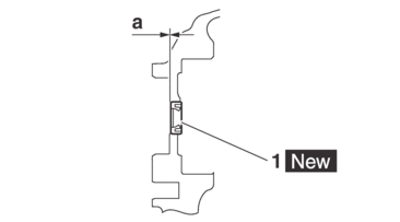
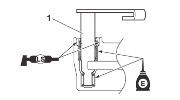
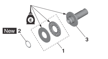
INSTALLING THE CLUTCH
1.Install:
-
Oil seal “1”

-
Circlip “2”

-
Check ball seat “3”
|
|
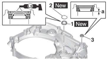
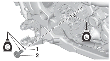
2.Install:
-
Dowel pin “1”
-
Gasket “2”

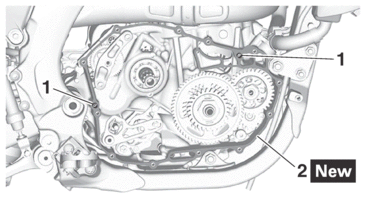
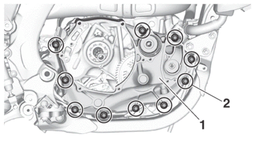
3.Install:
-
Crankcase cover (right) “1”
-
Crankcase cover bolt (right) “2”
|
|
4.Install:
-
Push lever shaft “1”
|
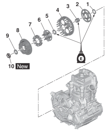
5.Install:
-
Washer “1”
-
Idle gear “2”
-
Collar “3”
-
Primary driven gear “4”
-
Washer “5”
-
Clutch boss “6”
-
Absorber “7”
-
Sleeve “8”
-
Washer “9”
-
Clutch boss nut “10”

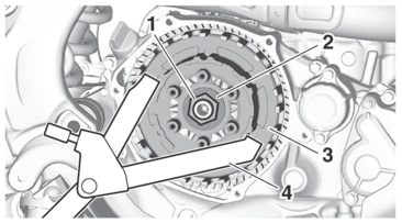
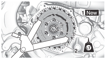
6.Tighten:
-
Clutch boss nut “1”
|
|

|
|
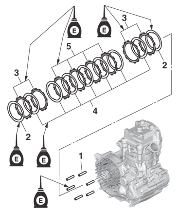
7.Install:
-
Collar “1”
-
Clutch plate 2 (thickness: 1.0 mm (0.04 in)) “2”
-
Friction plate 2 (painted) “3”
-
Clutch plate 1 (thickness: 1.4 mm (0.06 in)) “4”
-
Friction plate 1 (unpainted) “5”
|
8.Install:
-
Bearing “1”
-
Circlip “2”

(to the push rod 1 “3”)
|
9.Install:
-
Ball “1”
-
Push rod 1 “2”
|
10.Install:
-
Pressure plate 2 “1”
11.Install:
-
Spring retainer “1”
-
Clutch spring “2”
-
Pressure plate 1 “3”
-
Bolt (pressure plate 1) “4”
|
|
|
A. |
Engine side |
12.Install:
-
Gasket “1”

-
Clutch cover “2”
-
Clutch cover bolt (long) “3”
-
Clutch cover bolt (short) “4”
|
|