FRONT WHEEL

Removing the front wheel

Order

Job/Parts to remove

Q’ty

Remarks


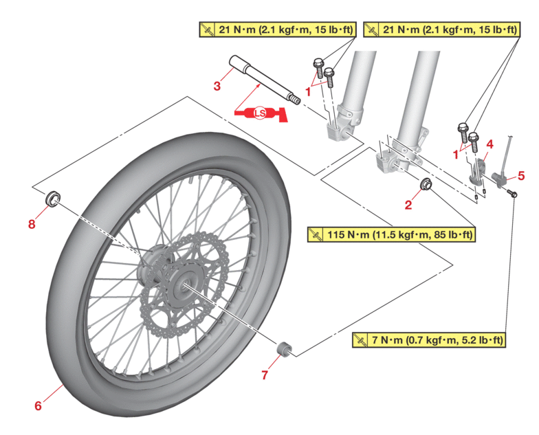
Use a maintenance stand to raise the front wheel off the ground.

1

Front wheel axle pinch bolt

4

Loosen.

2

Front wheel axle nut

1


3

Front wheel axle

1


4

Speed sensor bracket

1


5

Speed sensor

1


6

Front wheel

1


7

Collar (left)

1


8

Collar (right)

1


Disassembling the front wheel

Order

Job/Parts to remove

Q’ty

Remarks

1

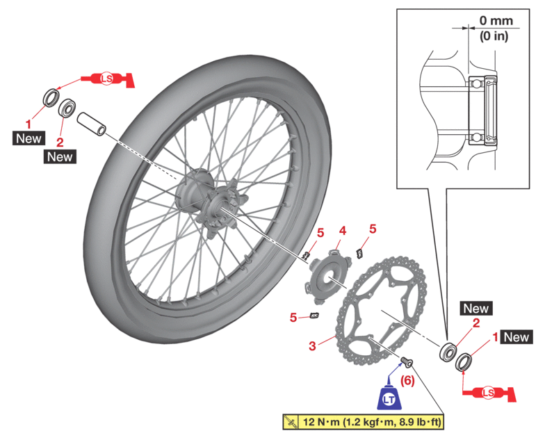
Oil seal

2


2

Bearing

2


3

Brake disc

1


4

Speed sensor rotor

1


5

Damper

3


REMOVING THE FRONT WHEEL

  • Keep any type of magnets (including magnetic pick-up tools, magnetic screwdrivers, etc.) away from the speed sensor or speed sensor rotor; otherwise, the sensor or rotor may be damaged, resulting in improper operation.

  • Do not drop the speed sensor rotor or subject it to shocks.

  • If any solvent gets on the speed sensor rotor, wipe it off immediately.

1.Use a maintenance stand to raise the front wheel off the ground.

Securely support the vehicle so that there is no danger of it falling over.

2.Remove:

  • Front wheel

CHECKING THE FRONT WHEEL SENSOR AND SENSOR ROTOR

  • The speed sensor cannot be disassembled. Do not attempt to disassemble it. If faulty, replace with a new one.

  • Keep magnets (including magnetic pick-up tools, magnetic screwdrivers, etc.) away from the speed sensor.

  • Do not drop or shock the speed sensor or the speed sensor rotor.

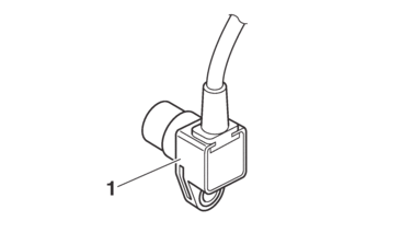
1.Check:

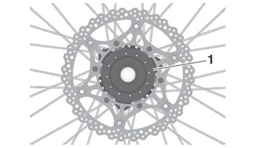
  • Front wheel sensor “1”

    Cracks/bends/distortion → Replace.

    Iron powder/dust → Clean.
2.Check:

  • Front wheel sensor rotor “1”

    Cracks/damage/scratches → Replace the front wheel sensor rotor.

    Iron powder/dust/solvent → Clean.

  • The wheel sensor rotor is installed on the inner side of the wheel hub.

  • When cleaning the wheel sensor rotor, be careful not to damage the surface of the sensor rotor.

3.Check:

  • Damper

    Cracks/damage → Replace the damper.
DISASSEMBLING THE FRONT WHEEL

1.Remove:

  • Oil seal

  • Bearing

a.Clean the outside of the front wheel hub.

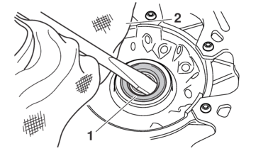
b.Remove the oil seals “1” with a flat-head screwdriver.

To prevent damaging the wheel, place a rag “2” between the screwdriver and the wheel surface.

c.Remove the bearings with a bearing puller.

CHECKING THE FRONT WHEEL

1.Check:

  • Front wheel axle

    Roll the front wheel axle on a flat surface.

    Bends → Replace.

Do not attempt to straighten a bent wheel axle.

2.Check:

3.Check:

4.Tighten:

  • Spoke

Refer to CHECKING AND TIGHTENING THE SPOKES.

  • Spoke

    2.5 N·m (0.25 kgf·m, 1.8 lb·ft)

After tightening the spokes, measure the wheel runout.

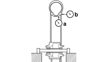
5.Measure:

  • Radial wheel runout “a”

  • Lateral wheel runout “b”

    Out of specification → Repair/replace.
  • Radial wheel runout limit

    2.0 mm (0.08 in)

  • Lateral wheel runout limit

    2.0 mm (0.08 in)

6.Check:

  • Collar

    Damage/wear → Replace.

7.Check:

  • Bearing

    Front wheel turns roughly or is loose → Replace the wheel bearings.

  • Oil seal

    Damage/wear → Replace.

ASSEMBLING THE FRONT WHEEL

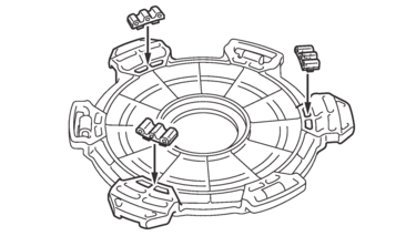
1.Install:

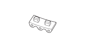
  • Damper

Install the dampers with their curves along the ones of the speed sensor rotor.

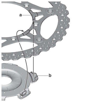
2.Install:

  • Speed sensor rotor

Snap the speed sensor rotor to the brake disc with the gaps of the rotor “b” aligned with the portion “a” of the brake disc.

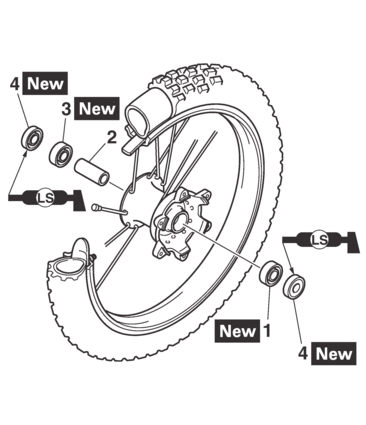
3.Install:

  • Bearing (left side) “1”

  • Spacer “2”

  • Bearing (right side) “3”

  • Oil seal “4”

  • Apply the lithium-soap-based grease to the oil seal lip when installing.

  • Left side of bearing shall be installed first.

  • Install the oil seal with its manufacture’s marks or numbers facing outward.

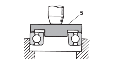
Install the bearing by pressing its outer race parallel.

Use a socket “5” that matches the diameter of the bearing outer race and that of the oil seal.

4.Install:

  • Brake disc

  • Brake disc bolt

  • Brake disc bolt

    12 N·m (1.2 kgf·m, 8.9 lb·ft)

    LOCTITE®

Tighten the bolts in stages and in a crisscross pattern.

5.Install:

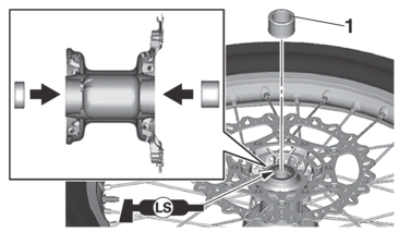
  • Collar “1”

Apply the lithium-soap-based grease on the oil seal lip.

INSTALLING THE FRONT WHEEL

1.Install:

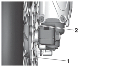
  • Front wheel

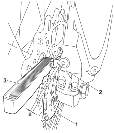
Install the brake disc “1” between the brake pads “2” correctly.

2.Install:

  • Front wheel sensor

  • Front wheel sensor bracket

  • Front wheel sensor bolt

    7 N·m (0.7 kgf·m, 5.2 lb·ft)

Make sure there are no foreign materials in the front wheel sensor rotor and front wheel sensor. Foreign materials cause damage to the front wheel sensor rotor and front wheel sensor.

When installing the front wheel sensor, check the wheel sensor lead for twists.

3.Install:

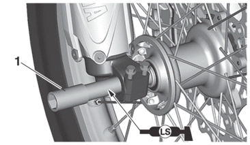
  • Front wheel axle “1”

Apply the lithium-soap-based grease to the front wheel axle.

4.Tighten:

  • Front wheel axle nut “1”

  • Front wheel axle nut

    115 N·m (11.5 kgf·m, 85 lb·ft)

Before tightening the front wheel axle nut, push down hard on the handlebar(s) several times and check if the front fork rebounds smoothly.

5.Tighten:

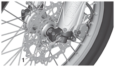
  • Front wheel axle pinch bolt “1”

  • Front wheel axle pinch bolt

    21 N·m (2.1 kgf·m, 15 lb·ft)

6.Measure:

  • Distance “a”

    (between the wheel sensor rotor “1” and front wheel sensor “2”)

    Out of specification → Check the wheel bearing for looseness, and the front wheel sensor and sensor rotor installation conditions (warpage caused by overtorque, wrong installation direction, rotor decentering, LOCTITE® on the mounting surface of the rotor, deformation caused by an impact during service and caught foreign materials). If there is any defective part, repair or replace the defective part.

  • Distance “a” (between the wheel sensor rotor and front wheel sensor)

    0.2–1.7 mm (0.008–0.067 in)

Measure the distance between the front wheel sensor rotor and front wheel sensor in several places in one rotation of the front wheel. Do not turn the front wheel while the thickness gauge “3” is installed. This may damage the front wheel sensor rotor and the front wheel sensor.

  • Thickness gauge

    90890-03268

  • Feeler gauge set

    YU-26900-9