CHASSIS
ADJUSTING THE FRONT DISC BRAKE
|
1.Check:
-
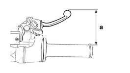
Brake lever position “a”
|
2.Remove:
-
Brake lever cover
3.Adjust:
-
Brake lever position
a.Loosen the locknut “1”.
b.Turn the adjusting bolt “2” until the specified brake lever position is obtained.
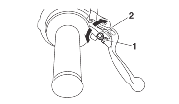
c.Tighten the locknut.
|
|
|
4.Install:
-
Brake lever cover
ADJUSTING THE REAR DISC BRAKE
1.Adjust:
-
Brake pedal position
a.Loosen the locknut “1”.
b.Turn the adjusting bolt “2” until the brake pedal is in the correct position.
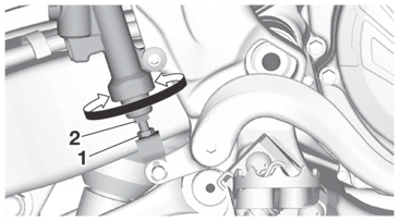
c.Tighten the locknut.
|
|
|
CHECKING THE BRAKE FLUID LEVEL
1.Stand the vehicle upright on a level surface.
|
2.Check:
-
Brake fluid level
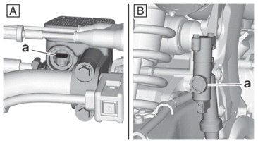
The minimum level mark “a” or below → Add.
|
|
A. |
Front brake |
|
B. |
Rear brake |
|
|
CHECKING THE FRONT BRAKE PADS
The following procedure applies to all of the brake pads.
1.Operate the brake.
2.Check:
-
Front brake pad
Wear indicator grooves “1” almost touch the brake disc → Replace the brake pads as a set.
Refer to FRONT BRAKE.
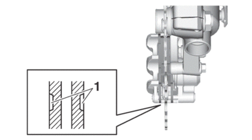
CHECKING THE REAR BRAKE PADS
The following procedure applies to all of the brake pads.
1.Operate the brake.
2.Check:
-
Rear brake pad
Wear indicator grooves “1” almost touch the brake disc → Replace the brake pads as a set.
Refer to REAR BRAKE.
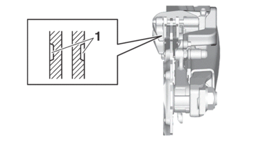
CHECKING THE FRONT BRAKE HOSE
1.Check:
-
Brake hose
Cracks/damage/wear → Replace.
2.Check:
-
Brake hose clamp
Loose connection → Tighten the clamp bolt.
3.Stand the vehicle upright and apply the front brake several times.
4.Check:
-
Brake hose
Brake fluid leaks → Replace the damaged brake hose.
Refer to FRONT BRAKE.
CHECKING THE REAR BRAKE HOSE
1.Check:
-
Brake hose
Cracks/damage/wear → Replace.
2.Check:
-
Brake hose holder
Loose connection → Tighten the holder bolt.
3.Hold the vehicle upright and apply the rear brake several times.
4.Check:
-
Brake hose
Brake fluid leakage → Replace the damaged hose.
Refer to REAR BRAKE.
CHECKING THE BRAKE OPERATION
1.Check:
-
Brake operation
Brake not working properly → Check the brake system.
Refer to FRONT BRAKE and REAR BRAKE.
|
BLEEDING THE HYDRAULIC BRAKE SYSTEM
|
1.Remove:
-
Brake master cylinder cap
-
Reservoir diaphragm
-
Reservoir float (front brake)
-
Protector (rear brake)
|
2.Bleed the brake system.
a.Fill the reservoir to the proper level with the recommended brake fluid.
b.Install the reservoir diaphragm.
c.Connect the plastic hose “1” to the bleed screw “2” securely, and place a container under the end of the plastic hose.
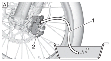

|
A. |
Front |
|
B. |
Rear |
d.Slowly apply the brake several times.
e.Fully pull the brake lever or fully press down the brake pedal and hold it in position.
f.Loosen the bleed screw.
|
g.Tighten the bleed screw and then release the brake lever or brake pedal.
h.Repeat steps (d) to (g) until all of the air bubbles have disappeared from the brake fluid in the plastic hose.
|
|
i.Tighten the bleed screw.
|
j.Pour brake fluid to the reservoir up to the specified level.
Refer to CHECKING THE BRAKE FLUID LEVEL.
|
DRIVE CHAIN SLACK
|
Checking the drive chain slack
1.Use a maintenance stand to raise the rear wheel off the ground.
|
2.Shift the transmission into the neutral position.
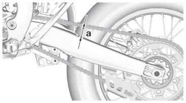
3.Pull the drive chain up above the drive chain guide installation bolt with a force of about 50 N (5.0 kgf, 37 lbf).
4.Check:
-
Drive chain slack “a”
Out of specification → Regulate.
|
|
Adjusting the drive chain slack
|
1.Adjust:
-
Drive chain slack
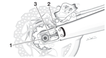
a.Loosen the wheel axle nut “1”.
b.Loosen both locknuts “2”.
c.Turn the adjusting bolt “3” until the specified drive chain slack is obtained.
|
d.Tighten the wheel axle nut.
|
e.Tighten the drive chain puller locknut.
|
LUBRICATING THE DRIVE CHAIN
The drive chain consists of many interacting parts. If the drive chain is not maintained properly, it will wear out quickly. Therefore, the drive chain should be serviced, especially when the vehicle is used in dusty areas.
This vehicle has a drive chain with small rubber O-rings between each side plate. Steam cleaning, high-pressure washing, certain solvents, and the use of a coarse brush can damage these O-rings. Therefore, use only kerosene to clean the drive chain. Wipe the drive chain dry and thoroughly lubricate it with engine oil or chain lubricant that is suitable for O-ring chains. Do not use any other lubricants on the drive chain since they may contain solvents that could damage the O-rings.
|
CHECKING AND ADJUSTING THE STEERING HEAD
1.Use a maintenance stand to raise the front wheel off the ground.
|
2.Check:
-
Steering head
Grasp the bottom of the front fork legs and gently rock the front fork.
Blinding/looseness → Adjust the steering head.
3.Remove:
-
Handlebar
Refer to HANDLEBAR.
-
Upper bracket
Refer to STEERING HEAD.
4.Adjust:
-
Steering head
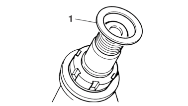
a.Remove the washer “1”.
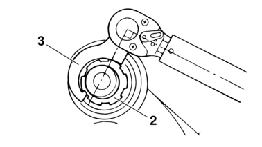
b.After loosening the ring nut “2” with a steering nut wrench “3”, tighten it to the specified torque.
|
|
|
c.Turn the front fork to the right and left a few times, and make sure that the steering rotates smoothly. If it does not turn smoothly, remove the lower bracket and check the upper and lower bearings.
Refer to STEERING HEAD.
d.Loosen the ring nut fully turn and then tighten it to specification with a steering nut wrench.
|
|
e.Check the steering head for looseness or binding by turning the front fork all the way in both directions. If any binding is felt, remove the lower bracket and check the upper and lower bearings.
Refer to STEERING HEAD.
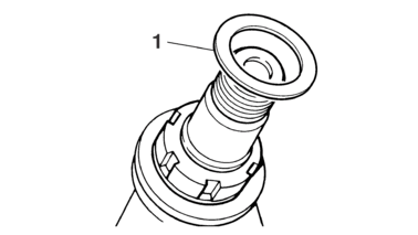
f.Install the washer “1”.
5.Install:
-
Upper bracket
Refer to STEERING HEAD.
-
Handlebar
Refer to HANDLEBAR.
LUBRICATING THE STEERING HEAD
1.Lubricate:
-
Upper bearing
-
Lower bearing
-
Bearing race
|
CHECKING THE FRONT FORK LEGS
1.Stand the vehicle upright on a level surface.
|
2.Check:
-
Inner tube
Damage/scratches → Replace.
-
Front fork leg
Oil leaks between inner tube and outer tube → Replace the oil seal.
3.Hold the vehicle upright and apply the front brake.
4.Check:
-
Front fork operation
Push down hard on the handlebar several times and check if the front fork rebounds smoothly.
Unsmooth operation → Correct or replace.
Refer to FRONT FORK.
5.Check:
-
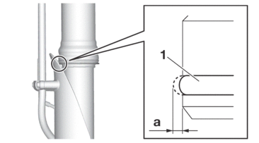
Protector guide “1”
Out of specification → Replace.
|
6.Remove:
-
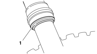
Protector
-
Dust seal “1”
|
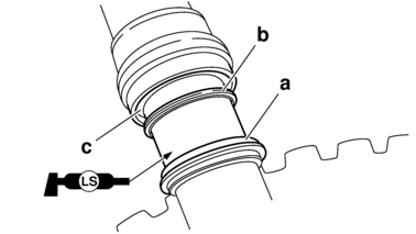
7.Clean:
-
Dust seal “a”
-
Scraper “b”
-
Oil seal “c”
|
ADJUSTING THE FRONT FORK LEGS
|
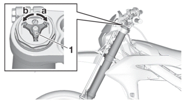
Rebound damping
|
1.Adjust:
-
Rebound damping
a.Turn the adjuster “1” in the direction of “a” or “b” to make an adjustment.
|
*With the adjusting screw fully turned in direction “a” |
|
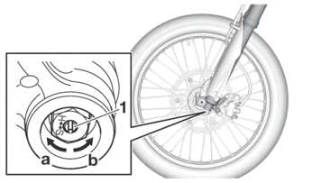
Compression damping
|
1.Adjust:
-
Compression damping
a.Turn the adjuster “1” in the direction of “a” or “b” to make an adjustment.
|
*With the adjusting screw fully turned in direction “a” |
|
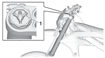
Air bleeding from front fork
|
1.Use a maintenance stand to raise the front wheel off the ground.
|
2.Remove the bleed screw “1” and release the internal pressure from the front fork.
3.Tighten:
-
Bleed screw

-
-
Bleed screw
1.3 N·m (0.13 kgf·m, 0.95 lb·ft)
-
CHECKING THE REAR SHOCK ABSORBER ASSEMBLY
1.Stand the vehicle upright on a level surface.
|
2.Check:
-
Rear shock absorber assembly
Gas leaks/oil leaks → Replace the rear shock absorber assembly.
Refer to REAR SHOCK ABSORBER ASSEMBLY.
3.Check:
-
Rear shock absorber assembly smooth action
-
Rear suspension link smooth action
Sit astride the seat and shake your body up and down several times to check whether the rear shock absorber assembly operates smoothly.
Unsmooth operation → Correct or replace.
Refer to REAR SHOCK ABSORBER ASSEMBLY.
ADJUSTING THE REAR SHOCK ABSORBER ASSEMBLY
Use a maintenance stand to raise the rear wheel off the ground.
|
Spring preload
|
1.Adjust:
-
Spring preload
a.Loosen the locknut “1”.
b.Loosen the adjuster “2” until there is some clearance between the spring and the adjuster.
c.Measure the spring free length “a”.
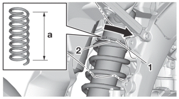
d.Turn the adjuster in the direction of “b” or “c” to make an adjustment.
|
|
|
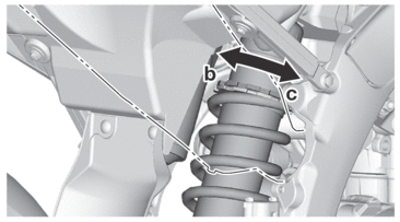
e.Tighten the locknut.
Rebound damping
|
1.Adjust:
-
Rebound damping
a.Turn the adjuster “1” in the direction of “a” or “b” to make an adjustment.
|
*With the adjusting screw fully turned in direction “a” |
|

Compression damping (for fast compression damping)
|
1.Adjust:
-
Compression damping (for fast compression damping)
a.Turn the adjuster “1” in the direction of “a” or “b” to make an adjustment.
|
*With the adjusting screw fully turned in direction “a” |
|
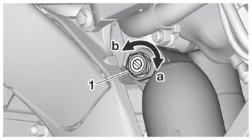
Compression damping (for slow compres-sion damping)
|
1.Adjust:
-
Compression damping (for slow compression damping)
a.Turn the adjuster “1” in the direction of “a” or “b” to make an adjustment.
|
*With the adjusting screw fully turned in direction “a” |
|

CHECKING THE SWINGARM OPERATION
1.Check:
-
Swingarm smooth action
-
Swingarm free play
Refer to SWINGARM.
LUBRICATING THE SWINGARM PIVOT
1.Lubricate:
-
Oil seal
-
Collar
|
Refer to INSTALLING THE SWINGARM.
CHECKING THE CONNECTING ARM AND RELAY ARM
CHECKING THE TIRES
1.Measure:
-
Tire pressure
Out of specification → Regulate.
|
|
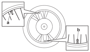
|
a. |
Bead stopper tightening nut |
|
b. |
Tire valve stem |
CHECKING AND TIGHTENING THE SPOKES
1.Check:
-
Spoke
Bend/damage → Replace.
Loose → Tighten.
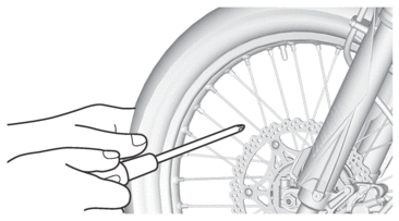
Tap the spokes with a screwdriver.
|
2.Tighten:
-
Spoke
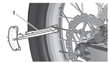
(with a spoke nipple wrench “1”)
|
|
|
CHECKING THE WHEELS
1.Check:
-
Wheel
Damage/out-of-round → Replace.
|
CHECKING THE WHEEL BEARINGS
1.Check:
-
Wheel bearing
Refer to CHECKING THE FRONT WHEEL and CHECKING THE REAR WHEEL.
CHECKING THE CHASSIS FASTENERS
Make sure that all nuts, bolts, and screws are properly tightened.
Refer to CHASSIS TIGHTENING TORQUES.
CHECKING AND LUBRICATING THE CABLES
The following procedure applies to all of the inner and outer cables.
|
1.Check:
-
Outer cable
Damage → Replace.
2.Check:
-
Cable operation
Rough movement → Lubricate.
|
|
LUBRICATING THE BRAKE LEVER
1.Lubricate the pivoting points and metal-to-metal moving parts of the following parts.
-
Brake lever
|
LUBRICATING THE CLUTCH LEVER
1.Lubricate the pivoting points and metal-to-metal moving parts of the following parts.
-
Clutch lever
|
LUBRICATING THE PEDAL
1.Lubricate the pivoting point and metal-to-metal moving parts of the pedal.
|
CHECKING THE SIDESTAND
1.Check:
-
Sidestand operation
Check that the sidestand moves smoothly.
Rough movement → Repair or replace.
LUBRICATING THE SIDESTAND
Lubricate the pivoting point and metal-to-metal moving parts of the sidestand.
|


