THROTTLE BODY
|
Removing the throttle body 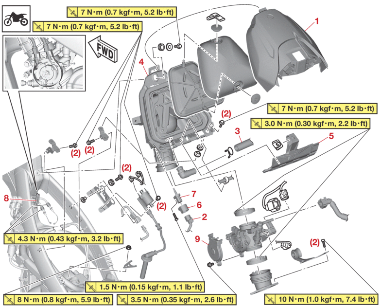 |
|||
|---|---|---|---|
|
Order |
Job/Parts to remove |
Q’ty |
Remarks |
|
|
Seat |
|
Refer to GENERAL CHASSIS. |
|
|
Side cover (left/right) |
|
Refer to GENERAL CHASSIS. |
|
|
Shroud (left/right) |
|
Refer to GENERAL CHASSIS. |
|
|
Fuel tank |
|
Refer to FUEL TANK. |
|
1 |
1 |
|
|
|
2 |
Intake air temperature sensor coupler |
1 |
Disconnect. |
|
3 |
Cylinder head breather hose |
1 |
|
|
4 |
Air filter case |
1 |
|
|
5 |
Air filter case assembly bracket |
1 |
|
|
6 |
Holder |
1 |
|
|
7 |
Intake air temperature sensor |
1 |
|
|
8 |
Cover |
1 |
|
|
9 |
Throttle cable cover |
1 |
|
|
Removing the throttle body 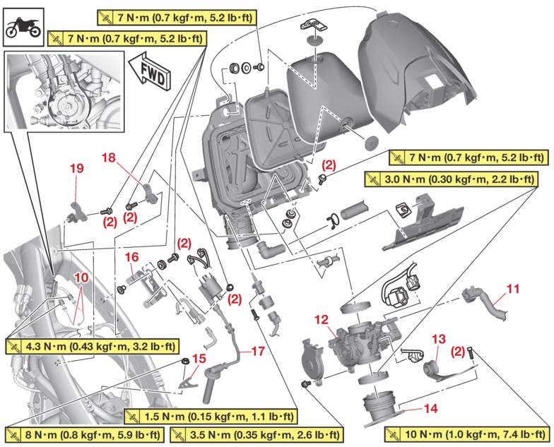 |
|||
|---|---|---|---|
|
Order |
Job/Parts to remove |
Q’ty |
Remarks |
|
10 |
Throttle cable |
2 |
|
|
11 |
Fuel hose |
1 |
|
|
12 |
Throttle body |
1 |
|
|
13 |
Exhaust pipe bracket |
1 |
|
|
14 |
Throttle body joint |
1 |
|
|
15 |
Holder |
1 |
|
|
16 |
Ignition coil bracket |
1 |
|
|
17 |
Ignition coil |
1 |
|
|
18 |
Air filter case bracket (right) |
1 |
|
|
19 |
Air filter case bracket (left) |
1 |
|
|
Removing the injector 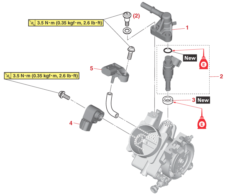 |
|||
|---|---|---|---|
|
Order |
Job/Parts to remove |
Q’ty |
Remarks |
|
1 |
Fuel inlet pipe |
1 |
|
|
2 |
Injector |
1 |
|
|
3 |
Gasket |
1 |
|
|
4 |
Throttle position sensor |
1 |
|
|
5 |
Intake air pressure sensor |
1 |
|
CHECKING THE INJECTOR
1.Check:
-
Injector
Obstruction → Replace, and check the fuel pump and the fuel injection system.
Refer to FUEL INJECTION SYSTEM.
Deposits → Replace.
Damage → Replace.
2.Check:
-
Injector resistance
Refer to CHECKING THE INJECTOR.
CHECKING THE THROTTLE BODY
1.Check:
-
Throttle body
Cracks/damage → Replace.
2.Check:
-
Fuel passages
Obstructions → Clean.
|
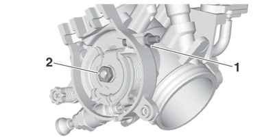
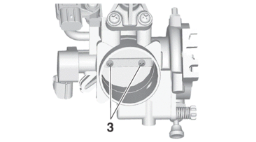
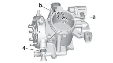
3.Check:
-
Idle screw “1” passage “a”
Obstruction → Blow out with compressed air.

4.Reset:
-
Use the diagnostic code number “87”.
Refer to DIAGNOSTIC CODE: SENSOR OPERATION TABLE.
|
CHECKING THE FUEL PRESSURE
1.Check:
-
Fuel pressure
a.Remove the side cover (left/right), the seat and the shroud (left/right).
Refer to GENERAL CHASSIS.
b.Remove the fuel tank bracket bolt and lift the fuel tank.
c.Disconnect the fuel hose from the fuel pump.
Refer to REMOVING THE FUEL TANK.
|
|
d.Connect the pressure gauge “1” and the fuel pressure adapter “2” to the fuel hose.
|
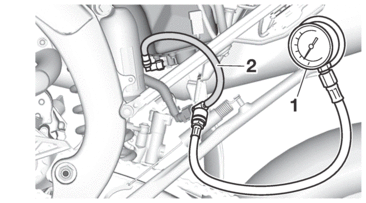
e.Start the engine.
f.Measure the fuel line pressure.
Out of specification → Replace the fuel pump.
|
ADJUSTING THE THROTTLE POSITION SENSOR
|
1.Check:
-
Throttle position sensor
Refer to CHECKING THE THROTTLE POSITION SENSOR INPUT VOLTAGE.
2.Adjust:
-
Throttle position sensor angle
a.Connect the Yamaha diagnostic tool.
Refer to YAMAHA DIAGNOSTIC TOOL.
|
b.Temporary tighten the throttle position sensor.
c.Check that the throttle grip is fully closed.
d.Connect the throttle position sensor to the wire harness.
e.Set the Yamaha diagnostic tool to “diagnostic mode”.
f.Choose the diagnostic code No. “01”.
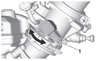
g.Adjust the throttle position sensor mounted angle until “11”–“14” appears on the Yamaha diagnostic tool.
h.After adjusting the throttle position sensor mounted angle, tighten the throttle position sensor screw “1”.
|
3.Reset:
-
Use the diagnostic code number “87”.
Refer to DIAGNOSTIC CODE: SENSOR OPERATION TABLE.
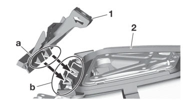
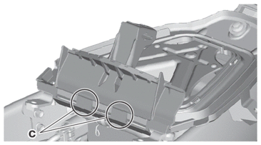
INSTALLING THE AIR FILTER CASE ASSEMBLY BRACKET
1.Install:
-
Air filter case assembly bracket “1”
|
