ELECTRICAL COMPONENTS
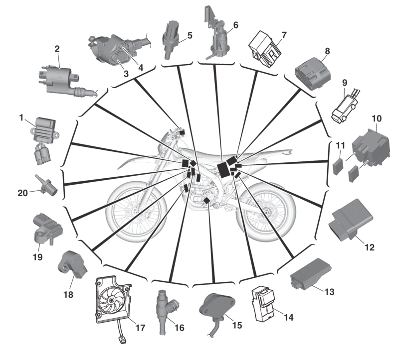
1.

Rectifier/regulator

2.

Ignition coil

3.

Mode switch

4.

Engine stop switch

5.

Coolant temperature sensor

6.

Fuel pump

7.

Radiator fan motor fuse

8.

Battery

9.

Resistor

10.

Starter relay

11.

Main fuse

12.

ECU (Engine Control Unit)

13.

CCU (Communication Control Unit)

14.

Radiator fan motor relay

15.

Gear position switch

16.

Injector

17.

Radiator fan motor

18.

Throttle position sensor

19.

Intake air pressure sensor

20.

Intake air temperature sensor

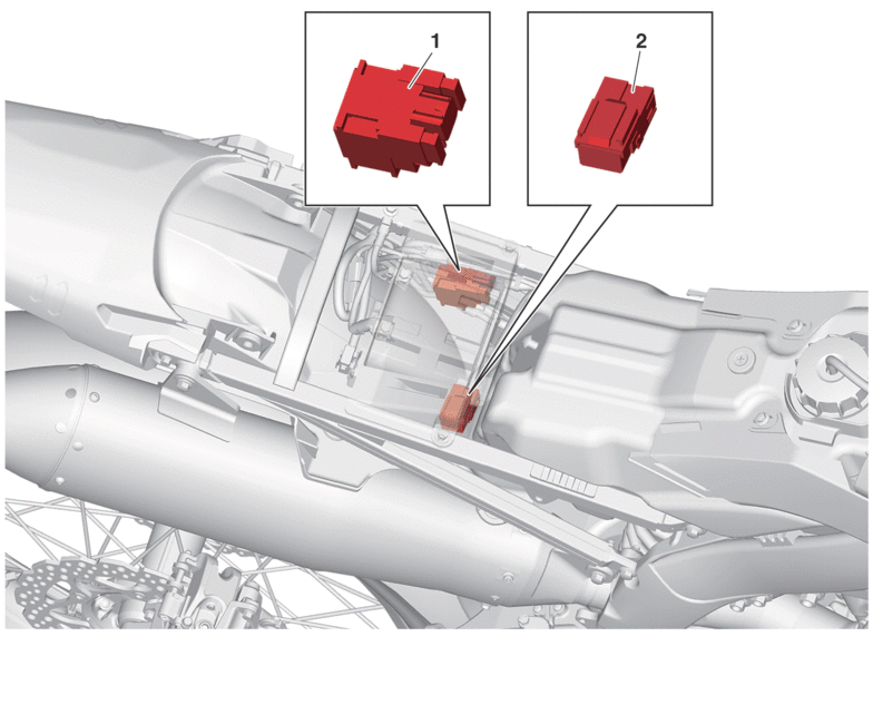
RELAY LOCATION CHART

  • Starter relay

  • Radiator fan motor relay

CHECKING THE SWITCHES
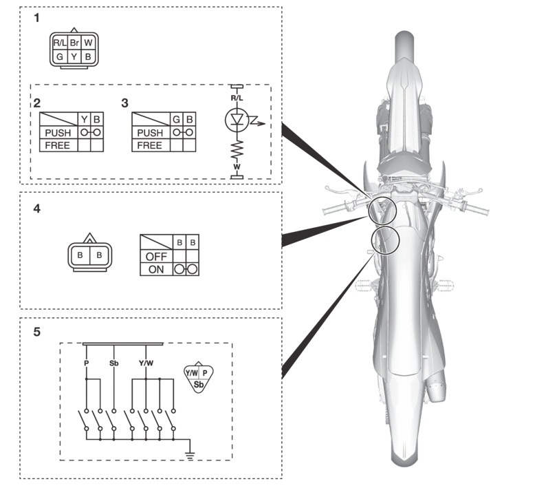
  • Handlebar switch (left)

  • Mode switch

  • Engine stop switch

  • Start switch

  • Gear position switch

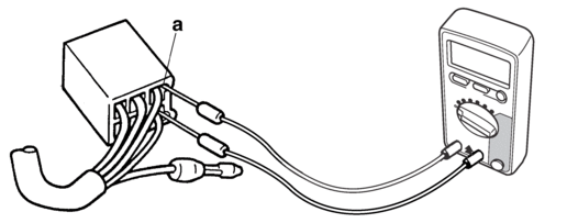
Check each switch for continuity with the digital circuit tester. If the continuity reading is incorrect, check the wiring connections and if necessary, replace the switch.

Never insert the tester probes into the coupler terminal slots. Always insert the probes from the opposite end “a” of the coupler, taking care not to loosen or damage the leads.

  • Digital circuit tester (CD732)

    90890-03243

  • Model 88 Multimeter with tachometer

    YU-A1927

When checking for continuity, switch back and forth between the switch positions a few times.

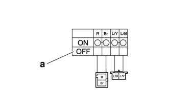
Terminal connections of the switch are shown in the terminal connection diagram below.

The switch positions “a” are shown in the far left column and the switch lead colors are shown in the top row in the switch illustration.

” indicates continuity between switch terminals (i.e., a closed circuit at each switch position).

The example illustration below shows that:

There is continuity between red and brown when the switch is “ON”.
CHECKING THE BULBS AND BULB SOCKETS

1.Remove:

  • Bulb

Be sure to hold the socket firmly when removing the bulb. Never pull the lead, otherwise it may be pulled out of the terminal in the coupler.

2.Check:

  • Bulb (for continuity)

    (with the digital circuit tester)

    No continuity → Replace.

  • Digital circuit tester (CD732)

    90890-03243

  • Model 88 Multimeter with tachometer

    YU-A1927

Before checking for continuity, set the digital circuit tester to “Ω” range.

3.Check:

  • Bulb socket (for continuity)

    (with the digital circuit tester)

    No continuity → Replace.

  • Digital circuit tester (CD732)

    90890-03243

  • Model 88 Multimeter with tachometer

    YU-A1927

Check each bulb socket for continuity in the same manner as described in the bulb section; however, note the following.

a.Install a good bulb into the bulb socket.

b.Connect the digital circuit tester probes to the respective leads of the bulb socket.

c.Check the bulb socket for continuity. If any of the readings indicate no continuity, replace the bulb socket.

CHECKING THE FUSES

The following procedure applies to all of the fuses.

1.Remove:

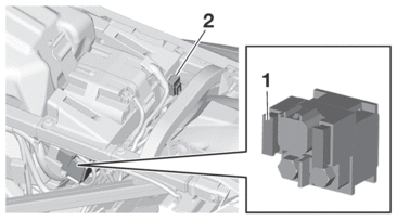
2.Check:

  • Fuse “1”

  • Radiator fan motor fuse “2”

a.Connect the digital circuit tester to the fuse and check the continuity.

Set the digital circuit tester selector to “Ω”.

  • Digital circuit tester (CD732)

    90890-03243

  • Model 88 Multimeter with tachometer

    YU-A1927

b.If the digital circuit tester indicates “O.L”, replace the fuse.

3.Replace:

  • Fuse

a.Install a new fuse of the correct amperage rating.

b.Push the start switch to verify if the electrical circuit is operational.

c.If the fuse immediately blows again, check the electrical circuit.

Fuses

Amperage rating

Q’ty

Main

15 A

1

Spare

15 A

1

Radiator fan motor

5 A

1

Never use a fuse with an amperage rating other than that specified. Improvising or using a fuse with the wrong amperage rating may cause extensive damage to the electrical system, cause the lighting and ignition systems to malfunction and could possibly cause a fire.

4.Install:

CHECKING AND CHARGING THE BATTERY

To avoid sparking, burns, fire, and explosion:

  • Charge battery only with specified charger.

  • Use battery only for specified product – no other use.

  • Do not place near fire or immerse in water.

  • Do not use battery if it has been dropped, subject to impact, or visibly damaged.

  • Do not disassemble or modify the battery, or short across its terminals.

To prevent damage to the battery and battery malfunction:

  • Be sure to charge the battery using only the specified battery charger. Do not use a charger designed for lead-acid batteries. Otherwise, the battery could be damaged, such as from a long period of excessive current or voltage exceeding 16 V.

  • Avoid excessive current discharge, such as pressing the start switch for a long time. Wait for more than 10 seconds before attempting to start again. Charge the battery again as soon as possible. A long state of discharge below 10 V will damage the battery.

  • Do not use the specified battery charger to charge a battery other than the lithium-ion battery. Otherwise, the battery or charger could be damaged.

  • Be careful not to drop the battery or subject it to strong impacts.

  • Avoid charging the battery at high temperatures of 65 °C (149 °F) or more or low temperatures under 0 °C (32 °F). A control feature preventing battery charging and discharging will temporarily intervene. The battery will discharge at 65 °C (149 °F) or more or low temperatures under -10 °C (14 °F).

  • If the battery is charged between 0 °C (32 °F)and 10 °C (50 °F), battery charging may stop halfway without the battery becoming fully charged even when the specified battery charger is used. If this occurs, disconnect the battery charger, and then resume charging again.

This model uses a lithium-ion battery. When new, the battery is supplied in sleep mode to minimize current discharging until first-time use. In the sleep mode, a voltage as low as approximately 0.1 V can be measured if voltage measurement is performed. As such the battery cannot be used, but this is not a malfunction. By activating the battery as follows, the sleep mode will be canceled and the battery can be used normally.

Charging (activation) steps

1.Remove:

2.Disconnect:

  • Battery lead

    (from the battery terminals)

First, disconnect the negative battery lead, and then the positive battery lead.

3.Remove:

  • Battery

4.Connect the battery charger (special tool) to the battery.

  • Lithium battery charger

    90890-05376

  • Lithium battery charger

    DBY-ACC51-70-02

  • For instructions on charging and handling the battery charger, refer to the battery charger’s instruction manual.

  • Once battery charging starts, the sleep mode is canceled.

5.Charge the battery until it is fully charged.

6.Install:

  • Battery

7.Connect:

  • Battery lead

    (to the battery terminals)

First, connect the positive battery lead, and then the negative battery lead.

8.Check:

  • Battery terminal

    Dirt → Clean with a wire brush.

    Loose connection → Connect properly.

9.Lubricate:

  • Battery terminal

  • Recommended lubricant

    Dielectric grease

10.Install:

Checking the battery

The battery has a limited service life. If the battery cannot be charged or it is determined that the battery cannot be used after checking the battery, it should be replaced. When replacing the battery, be sure to use a Yamaha genuine lithium-ion battery.

Do not check the battery at high temperature of 65 °C (149 °F) or more or low temperatures below 10 °C (50 °F). Otherwise, the control feature preventing battery charging and discharging will temporarily intervene.

1.Check:

  • Battery

a.If the battery is hot, wait until the battery has cooled down to the ambient temperature.

b.Measure the voltage between the battery terminals.

13.25 V or more → The battery is normal. Checking is finished.

Less than 13.25 V → Go to step (c).

c.Connect the battery charger (special tool) to the battery and charge it.

  • Lithium battery charger

    90890-05376

  • Lithium battery charger

    DBY-ACC51-70-02

For instructions on charging and handling the battery charger, refer to the battery charger’s instruction manual.

d.If the battery is hot, wait until the battery has cooled down to the ambient temperature.

e.Measure the voltage between the battery terminals.

13.25 V or more → The battery is normal. Checking is finished.

10 V or more and less than 13.25 V → Perform from step (c) again.

Less than 10 V → Replace the battery.

Before replacing the battery, make sure that the battery temperature is proper (temperature not more than 65 °C (149 °F) or less than 0 °C (32 °F)). Otherwise, wait until the battery temperature is proper and perform the procedure from step (c) again.

REPLACING THE ECU (Engine Control Unit)

1.Turn off the main switch.

2.Replace the ECU (Engine Control Unit).

Refer to GENERAL CHASSIS.

3.Reset the ECU (Engine Control Unit).

Use the diagnostic code number “87”.

Refer to DIAGNOSTIC CODE: SENSOR OPERATION TABLE.

  • Yamaha diagnostic tool USB (US)

    90890-03275

  • Yamaha diagnostic tool (A/I)

    90890-03273

4.Check:

  • Engine idling speed

    Start the engine, warm it up, and then measure the engine idling speed.

  • Engine idling speed

    1900–2100 r/min

CHECKING THE RELAYS

Check each switch for continuity with the digital circuit tester. If the continuity reading is incorrect, replace the relay.

  • Digital circuit tester (CD732)

    90890-03243

  • Model 88 Multimeter with tachometer

    YU-A1927

1.Disconnect the relay from the wire harness.

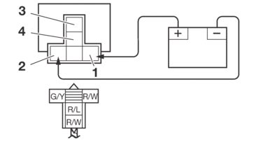
2.Connect the digital circuit tester (Ω) and battery (12 V) to the relay terminal as shown.

Check the relay operation.

Out of specification → Replace.

Starter relay
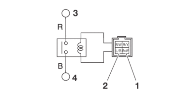
1.

Positive battery terminal

2.

Negative battery terminal

3.

Positive tester probe

4.

Negative tester probe

  • Result

    Continuity

    (between “3” to “4”)

Radiator fan motor relay

1.

Positive battery terminal

2.

Negative battery terminal

3.

Positive tester probe

4.

Negative tester probe

  • Result

    Continuity

    (between “3” to “4”)

CHECKING THE IGNITION SPARK GAP

1.Check:

  • Ignition spark gap

    Out of specification → Perform the ignition system troubleshooting, starting with step (5).

    Refer to TROUBLESHOOTING.

  • Minimum ignition spark gap

    6.0 mm (0.24 in)

If the ignition spark gap is within specification, the ignition system circuit is operating normally.

a.Remove the spark plug cap from the spark plug.

b.Connect the ignition checker “1” as shown.

  • Ignition checker

    90890-06754

  • Oppama pet–4000 spark checker

    YM-34487

c.Crank the engine, and measure the ignition spark gap “a”.
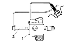
2.

Spark plug cap

d.Crank the engine, and gradually increase the spark gap until a misfire occurs.

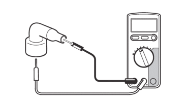
CHECKING THE SPARK PLUG CAP

1.Remove:

  • Spark plug cap

    (from the spark plug lead)

2.Check:

  • Spark plug cap resistance

    Out of specification → Replace.

  • Resistance

    7.50–12.50 kΩ

a.Connect the digital circuit tester (Ω) to the spark plug cap.

  • Digital circuit tester (CD732)

    90890-03243

  • Model 88 Multimeter with tachometer

    YU-A1927

b.Measure the spark plug cap resistance.

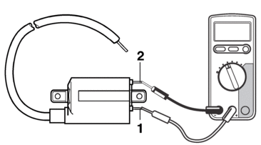
CHECKING THE IGNITION COIL

1.Disconnect:

  • Ignition coil terminal

    (from the wire harness)

  • Spark plug cap

    (from the ignition coil)

2.Check:

  • Primary coil resistance

    Out of specification → Replace.

  • Primary coil resistance

    1.98–2.42 Ω

a.Connect the digital circuit tester (Ω) to the ignition coil.

  • Digital circuit tester (CD732)

    90890-03243

  • Model 88 Multimeter with tachometer

    YU-A1927

  • Positive tester probe →

    Ignition coil terminal 1 “1”

  • Negative tester probe →

    Ignition coil terminal 2 “2”

b.Measure the primary coil resistance.

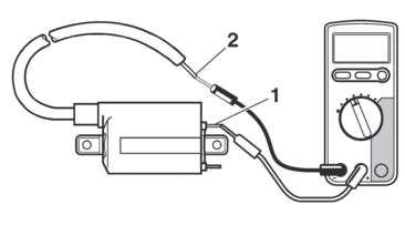
3.Check:

  • Secondary coil resistance

    Out of specification → Replace.

  • Secondary coil resistance

    14.64–21.96 kΩ

a.Connect the digital circuit tester (Ω) to the ignition coil.

  • Digital circuit tester (CD732)

    90890-03243

  • Model 88 Multimeter with tachometer

    YU-A1927

  • Positive tester probe →

    Ignition coil terminal 1 “1”

  • Negative tester probe →

    Spark plug lead “2”

b.Measure the secondary coil resistance.

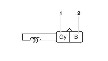
CHECKING THE CRANKSHAFT POSITION SENSOR

1.Disconnect:

  • Crankshaft position sensor coupler

    (from the wire harness)

2.Check:

  • Crankshaft position sensor resistance

    Out of specification → Replace.

  • Crankshaft position sensor resistance

    228–342 Ω

a.Connect the digital circuit tester (Ω) to the crankshaft position sensor coupler.

  • Digital circuit tester (CD732)

    90890-03243

  • Model 88 Multimeter with tachometer

    YU-A1927

  • Positive tester probe →

    Gray “1”

  • Negative tester probe →

    Black “2”

b.Measure the crankshaft position sensor resistance.

CHECKING THE LEAN ANGLE SENSOR

1.Check:

  • Mounted condition of ECU

    Improperly mounted → Remount.

  • The lean angle sensor is built into the ECU.

  • The lean angle sensor stops the engine in case of a turnover.

  • To ensure that the lean angle sensor operates correctly, do not change the installed condition of the ECU.

CHECKING THE STARTER MOTOR OPERATION

1.Check:

  • Starter motor operation

    Does not operate → Perform the electric starting system troubleshooting, starting with step (3).

    Refer to TROUBLESHOOTING.

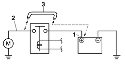
a.Connect the positive battery terminal “1” and starter motor lead “2” with a jumper lead “3”.

  • A wire that is used as a jumper lead must have at least the same capacity of the battery lead, otherwise the jumper lead may burn.

  • This check is likely to produce sparks, therefore, make sure no flammable gas or fluid is in the vicinity.

b.Check the starter motor operation.

CHECKING THE STATOR COIL

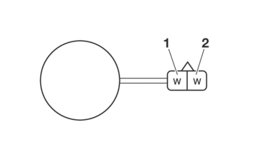
1.Disconnect:

  • Stator coil assembly coupler

    (from the wire harness)

2.Check:

  • Stator coil assembly

a.Connect the digital circuit tester (Ω) to the stator coil assembly coupler.

  • Digital circuit tester (CD732)

    90890-03243

  • Model 88 Multimeter with tachometer

    YU-A1927

  • Positive tester probe →

    White “1”

  • Negative tester probe →

    White “2”

b.Check the stator coil for continuity.

c.If there is no continuity, replace the stator coil assembly.

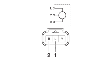
CHECKING THE RECTIFIER/REGULATOR

1.Check:

  • Rectifier/regulator output voltage

    Out of specification → Replace.

  • Regulated voltage (DC)

    14.0–14.8 V

a.Set the digital tachometer to the ignition coil.

  • Digital tachometer

    90890-06760

  • Digital tachometer

    YU-39951-B

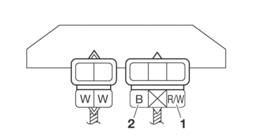
b.Connect the digital circuit tester (DCV) to the rectifier/regulator coupler.

  • Digital circuit tester (CD732)

    90890-03243

  • Model 88 Multimeter with tachometer

    YU-A1927

  • Positive tester probe →

    Red/White “1”

  • Negative tester probe →

    Black “2”

c.Start the engine and let it run at about 5000 r/min.

d.Measure the output voltage.

CHECKING THE SPEED SENSOR

1.Check:

  • Speed sensor output voltage

    Out of specification → Replace.

  • Output voltage reading cycle

    0.6 V to 4.8 V to 0.6 V to 4.8 V

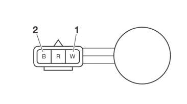
a.Connect the test harness to the speed sensor coupler and wire harness.

b.Connect the digital circuit tester (DC) to the test harness.

  • Digital circuit tester (CD732)

    90890-03243

  • Model 88 Multimeter with tachometer

    YU-A1927

  • Test harness– speed sensor 5TJ (3P)

    90890-03228

  • Test harness– speed sensor 5TJ (3P)

    YU-03228

  • Positive tester probe →

    White “1”

  • Negative tester probe →

    Black “2”

c.Push the start switch.

d.Elevate the front wheel and slowly turn it.

e.Measure the voltage (DC 5 V). With the front wheel slowly rotating, voltage alternates between 0 V and 5 V.

CHECKING THE FUEL SENDER

1.Disconnect:

  • Starter motor lead

    (from the starter relay)

2.Connect:

  • Fuel pump coupler

3.Push the start switch.

4.Check:

  • Fuel level warning light

    Out of specification → Replace the fuel pump.

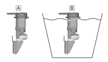
  • Fuel pump is atmosphere “A”
    → Fuel level warning light comes on

  • Fuel pump is soaked in fuel “B”
    → Fuel level warning light goes off

CHECKING THE RESISTOR

1.Disconnect:

  • Resistor coupler

    (from the wire harness)

2.Check:

  • Resistor resistance

    Out of specification → Replace the resistor.

  • Resistor resistance

    64.6–71.4 Ω

a.Connect the digital circuit tester (Ω) to the resistor as shown.

  • Digital circuit tester (CD732)

    90890-03243

  • Model 88 Multimeter with tachometer

    YU-A1927

  • Positive tester probe →

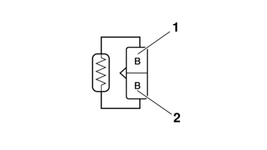
    Black “1”

  • Negative tester probe →

    Black “2”

b.Measure the resistance of the resistor.

CHECKING THE RADIATOR FAN MOTOR

1.Check:

  • Radiator fan motor

    Faulty/rough movement → Replace.

a.Disconnect the radiator fan motor coupler from the wire harness.

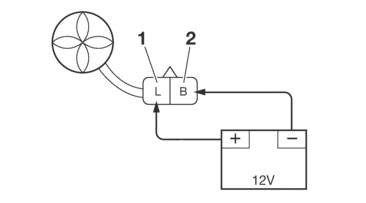
b.Connect the battery (DC 12 V) as shown.

  • Positive battery terminal →

    Blue “1”

  • Negative battery terminal →

    Black “2”

c.Measure the radiator fan motor movement.

CHECKING THE COOLANT TEMPERATURE SENSOR

1.Remove:

  • Coolant temperature sensor

  • Handle the coolant temperature sensor with special care.

  • Never subject the coolant temperature sensor to strong shocks. If the coolant temperature sensor is dropped, replace it.

2.Check:

  • Coolant temperature sensor resistance

    Out of specification → Replace.

  • Coolant temperature sensor resistance

    2513–2777 Ω at 20 °C (2513–2777 Ω at 68 °F)

  • Coolant temperature sensor resistance

    210–221 Ω at 100 °C (210–221 Ω at 212 °F)

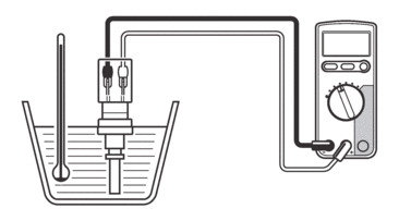
a.Connect the digital circuit tester (Ω) to the coolant temperature sensor.

  • Digital circuit tester (CD732)

    90890-03243

  • Model 88 Multimeter with tachometer

    YU-A1927

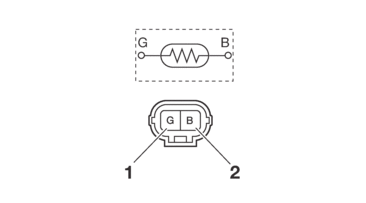
  • Positive tester probe →

    Green “1”

  • Negative tester probe →

    Black “2”

b.Immerse the coolant temperature sensor in a container filled with coolant.

Make sure the coolant temperature sensor terminals do not get wet.

c.Place a thermometer in the coolant.

d.Slowly heat the coolant, and then let it cool to the specified temperature indicated in the table.

e.Check the coolant temperature sensor for continuity at the temperatures indicated in the table.
CHECKING THE THROTTLE POSITION SENSOR INPUT VOLTAGE

1.Check:

  • Throttle position sensor input voltage

    Out of specification → Replace the throttle position sensor.

  • Throttle position sensor input voltage

    4–6 V

a.Connect the test harness to the throttle position sensor coupler and the wire harness.

b.Connect the digital circuit tester (DCV) to the test harness.

  • Digital circuit tester (CD732)

    90890-03243

  • Model 88 Multimeter with tachometer

    YU-A1927

  • Test harness (3P) – sub throttle position sensor

    90890-03214

  • Positive tester probe →

    Blue “1”

  • Negative tester probe →

    Black “2”

c.Start the engine.

d.Measure the throttle position sensor input voltage.

If the throttle position sensor is replaced, reset the ECU using the diagnostic code number “87”.

Refer to DIAGNOSTIC CODE: SENSOR OPERATION TABLE.

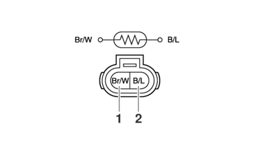
CHECKING THE INTAKE AIR TEMPERATURE SENSOR

1.Remove:

  • Intake air temperature sensor

    (from the air filter case)

  • Handle the intake air temperature sensor with special care.

  • Never subject the intake air temperature sensor to strong shocks. If the intake air temperature sensor is dropped, replace it.

2.Check:

  • Intake air temperature sensor resistance

    Out of specification → Replace.

  • Intake air temperature sensor resistance

    5400–6600 Ω at 0 °C (5400–6600 Ω at 32 °F)

  • Intake air temperature sensor resistance

    290–390 Ω at 80 °C (290–390 Ω at 176 °F)

a.Connect the digital circuit tester (Ω) to the intake air temperature sensor terminal.

  • Digital circuit tester (CD732)

    90890-03243

  • Model 88 Multimeter with tachometer

    YU-A1927

  • Positive tester probe →

    Brown/White “1”

  • Negative tester probe →

    Black/Blue “2”

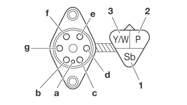
CHECKING THE GEAR POSITION SWITCH

1.Remove:

  • Gear position switch

2.Check:

  • Gear position switch

    Out of specification → Replace.

  • Digital circuit tester (CD732)

    90890-03243

  • Model 88 Multimeter with tachometer

    YU-A1927

  • Continuity

    Positive tester probe →

    Sky blue “1”

    Negative tester probe →

    Sensor terminal “a”

  • Continuity

    Positive tester probe →

    Pink “2”

    Negative tester probe →

    Sensor terminal “b”

  • Continuity

    Positive tester probe →

    Pink “2”

    Negative tester probe →

    Sensor terminal “c”

  • Continuity

    Positive tester probe →

    Yellow/White “3”

    Negative tester probe →

    Sensor terminal “d”

  • Continuity

    Positive tester probe →

    Yellow/White “3”

    Negative tester probe →

    Sensor terminal “e”

  • Continuity

    Positive tester probe →

    Yellow/White “3”

    Negative tester probe →

    Sensor terminal “f”

  • Continuity

    Positive tester probe →

    Yellow/White “3”

    Negative tester probe →

    Sensor terminal “g”

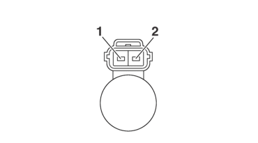
CHECKING THE INJECTOR

1.Remove:

2.Check:

  • Fuel injector resistance

    Out of specification → Replace.

  • Resistance

    12.0 Ω

a.Disconnect the fuel injector coupler from the fuel injector.

b.Connect the digital circuit tester (Ω) to the fuel injector coupler.

  • Digital circuit tester (CD732)

    90890-03243

  • Model 88 Multimeter with tachometer

    YU-A1927

  • Positive tester probe →

    Injector terminal “1”

  • Negative tester probe →

    Injector terminal “2”

c.Measure the fuel injector resistance.