ENGINE REMOVAL

|
Removing the exhaust pipe 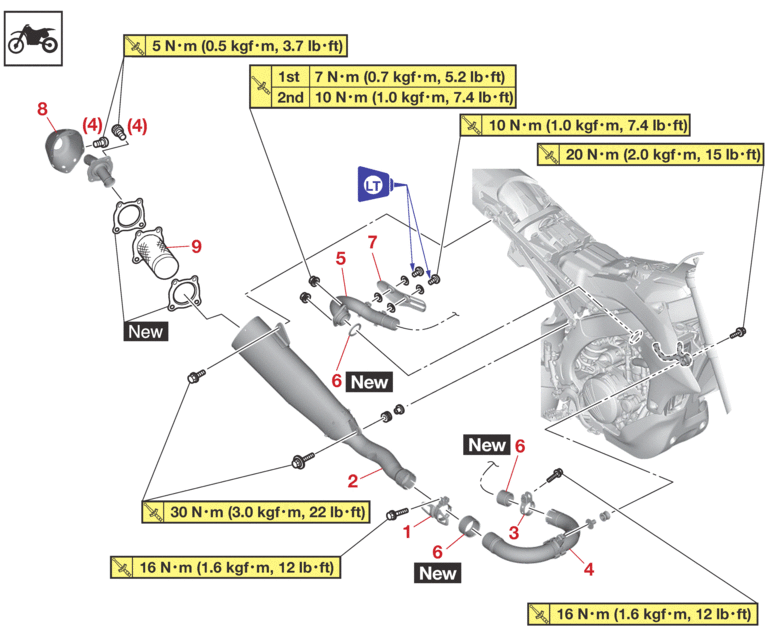 |
|||
|---|---|---|---|
|
Order |
Job/Parts to remove |
Q’ty |
Remarks |
|
|
|
|
Refer to INSTALLING THE EXHAUST PIPE AND MUFFLER. |
|
|
Side cover (right) |
|
Refer to GENERAL CHASSIS. |
|
1 |
Silencer clamp |
1 |
Loosen. |
|
2 |
Silencer |
1 |
|
|
3 |
Exhaust pipe 2 clamp |
1 |
Loosen. |
|
4 |
Exhaust pipe 2 |
1 |
|
|
5 |
Exhaust pipe 1 |
1 |
|
|
6 |
Gasket |
3 |
|
|
7 |
Exhaust pipe 1 protector |
1 |
|
|
8 |
Silencer cap |
1 |
|
|
9 |
Spark arrester |
1 |
|
|
Removing the electronic parts 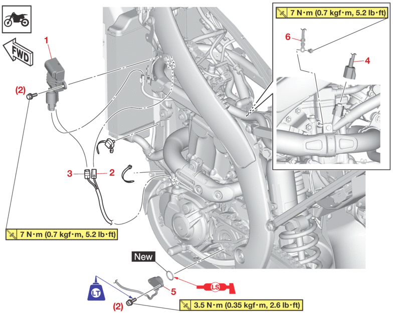 |
|||
|---|---|---|---|
|
Order |
Job/Parts to remove |
Q’ty |
Remarks |
|
|
|
|
Use a maintenance stand to raise the front wheel off the ground. |
|
|
Seat |
|
Refer to GENERAL CHASSIS. |
|
|
Side cover (left) |
|
Refer to GENERAL CHASSIS. |
|
|
Shroud (left) |
|
Refer to GENERAL CHASSIS. |
|
1 |
Rectifier/regulator |
1 |
|
|
2 |
Stator coil assembly coupler |
1 |
Disconnect. |
|
3 |
Crankshaft position sensor coupler |
1 |
Disconnect. |
|
4 |
Coolant temperature sensor coupler |
1 |
|
|
5 |
Gear position switch |
1 |
|
|
6 |
Engine ground lead terminal |
1 |
Disconnect. |
|
Removing the engine 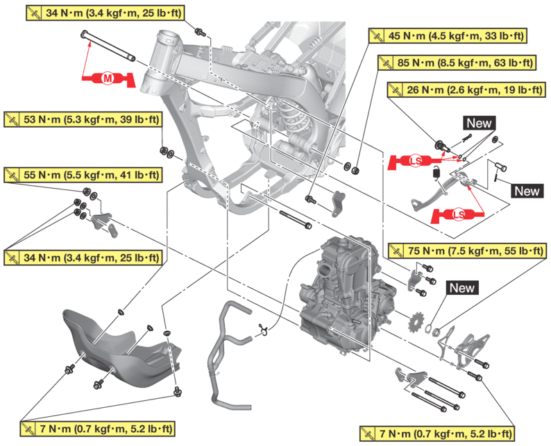 |
|||
|---|---|---|---|
|
Order |
Job/Parts to remove |
Q’ty |
Remarks |
|
|
|
|
Use a maintenance stand to raise the front wheel off the ground. |
|
|
Seat/Side cover (left/right)/Shroud (left/right) |
|
Refer to GENERAL CHASSIS. |
|
|
Fuel tank |
|
Refer to FUEL TANK. |
|
|
Exhaust pipe/Silencer |
|
Refer to ENGINE REMOVAL. |
|
|
Air filter case/Throttle body |
|
Refer to THROTTLE BODY. |
|
|
Clutch cable |
|
Refer to CLUTCH. |
|
|
Shift pedal/Drive chain |
|
Refer to SHIFT SHAFT. Refer to CHAIN DRIVE. |
|
|
Starter motor lead |
|
Disconnect. Refer to ELECTRIC STARTER. |
|
|
Spark plug cap |
|
Disconnect. Refer to THROTTLE BODY. |
|
|
Radiator hose 1/3/4 |
|
Refer to RADIATOR. |
|
Removing the engine 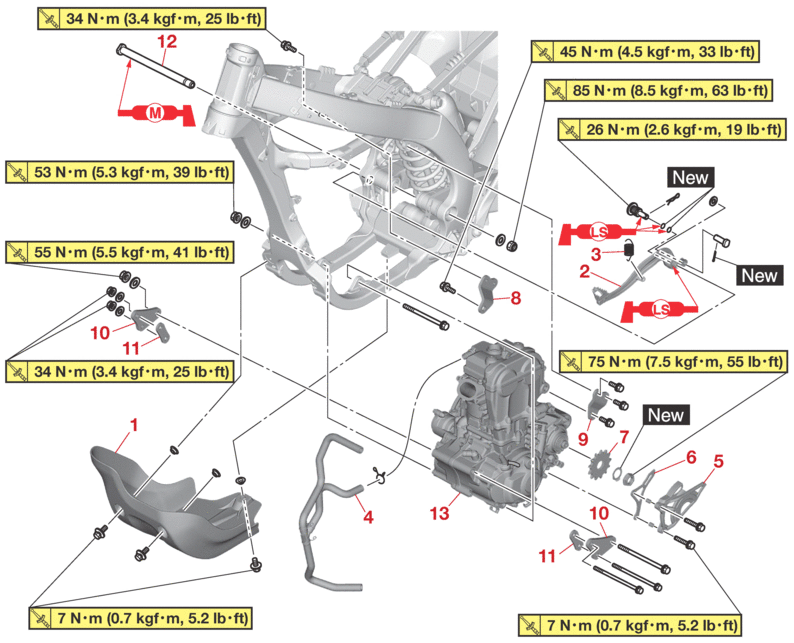 |
|||
|---|---|---|---|
|
Order |
Job/Parts to remove |
Q’ty |
Remarks |
|
1 |
Engine guard |
1 |
|
|
2 |
Brake pedal |
1 |
|
|
3 |
Spring |
1 |
|
|
4 |
Cylinder head breather hose |
1 |
|
|
5 |
Drive sprocket cover |
1 |
|
|
6 |
Drive chain guide |
1 |
|
|
7 |
Drive sprocket |
1 |
|
|
8 |
Upper engine bracket (right) |
1 |
|
|
9 |
Upper engine bracket (left) |
1 |
|
|
10 |
Lower engine bracket (outside) |
2 |
|
|
11 |
Lower engine bracket (inside) |
2 |
|
|
12 |
Pivot shaft |
1 |
|
|
13 |
Engine |
1 |
|
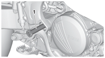
REMOVING THE ENGINE
1.Remove:
-
Exhaust pipe 2
|

2.Remove:
-
Pivot shaft “1”
|
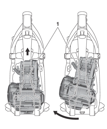
3.Remove:
-
Engine “1”
(from the right side)
|
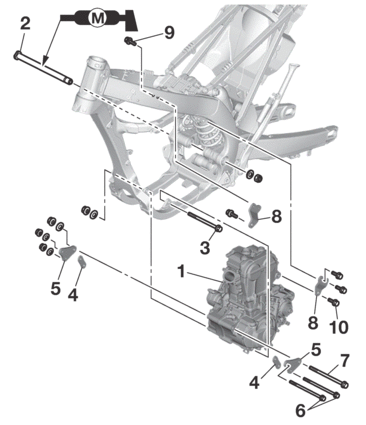
INSTALLING THE ENGINE
1.Install:
-
Engine “1”
(from the right side)
-
Pivot shaft “2”
|

-
Engine mounting bolt (lower side) “3”
|
-
Lower engine bracket (inside) “4”
-
Lower engine bracket (outside) “5”
-
Engine bracket bolt (front side) “6”
|
-
Engine mounting bolt (front side) “7”
|
-
Upper engine bracket “8”
-
Engine bracket bolt (upper side) “9”
|
-
Engine mounting bolt (upper side) “10”
|
|

|
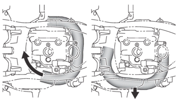
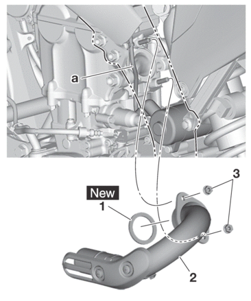
INSTALLING THE EXHAUST PIPE AND MUFFLER
1.Install:
-
Gasket “1”

-
Exhaust pipe 1 “2”
-
Nut (exhaust pipe 1) “3”
|

|
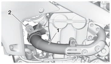
2.Install:
-
Clamp
-
Exhaust pipe 2 “1”
-
Bolt (exhaust pipe 2) “2”
|
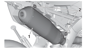
3.Install:
-
Clamp
-
Silencer “1”
-
Bolt (silencer) “2”
|
|
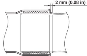
4.Tighten:
-
Bolt (exhaust pipe 2)
|
-
Clamp “1”
|
|
|
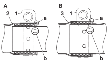
A. |
Exhaust pipe 1 and exhaust pipe 2 |
|
B. |
Exhaust pipe 2 and silencer |