ENGINE
ADJUSTING THE VALVE CLEARANCE
|
1.Remove:
-
Seat
-
Side cover (left/right)
-
Shroud (left/right)
Refer to GENERAL CHASSIS.
-
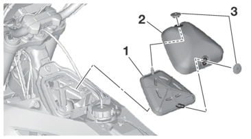
Fuel tank
Refer to FUEL TANK.
2.Remove:
-
Spark plug
-
Cylinder head cover
Refer to CAMSHAFT.
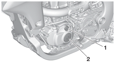
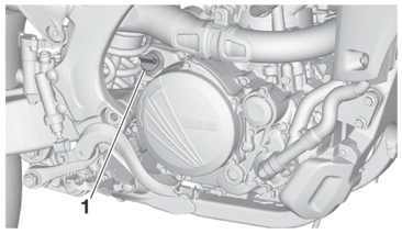
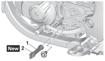
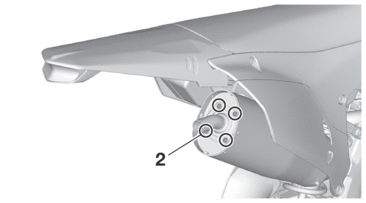
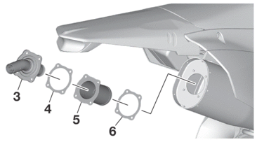
3.Remove:
-
Timing mark accessing screw “1”
-
Crankshaft end accessing screw “2”
-
O-ring
4.Check:
-
Valve clearance
Out of specification → Regulate.
|

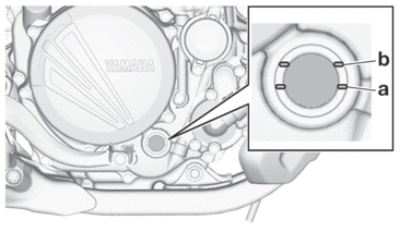
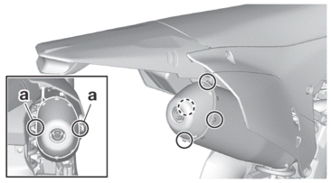
a.Turn the crankshaft counterclockwise with a wrench.
b.Align the top dead center (TDC) mark “a” on the generator rotor with the alignment mark “b” on the crankcase cover.
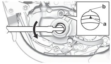
|
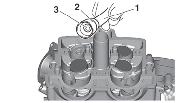
c.Measure the valve clearance using a thickness gauge “1”.
|

|
5.Adjust:
-
Valve clearance
a.Remove the camshaft (intake and exhaust).
Refer to CAMSHAFT.
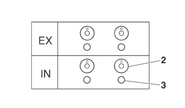
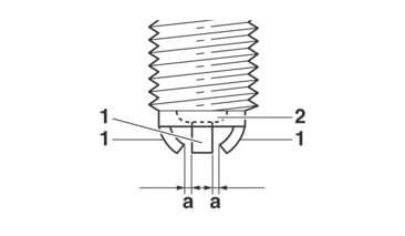
b.Remove the valve lifter “2” and the adjusting pad “3” with a valve lapper “1”.
|
|
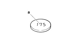
c.Check the number on the originally installed adjusting pad.
|
d.Select an adjusting pad with a proper valve clearance from the adjusting pad selection table.
|

|
Last digit of pad number |
Rounded value |
|---|---|
|
0, 1 or 2 |
0 |
|
4, 5 or 6 |
5 |
|
8 or 9 |
10 |
Example:
Pad number = 148
Rounded value = 150
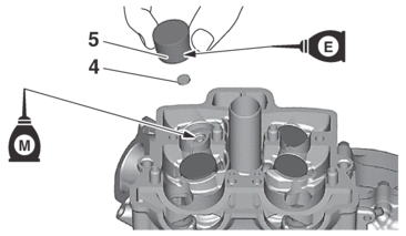
e.Install the new adjusting pads “4” and the valve lifters “5”.
|

|
f.Install the camshafts (exhaust and intake).
Refer to CAMSHAFT.
g.Measure the valve clearance again.
h.If the valve clearance is out of specification, repeat adjusting the valve clearance until it is within specification.
VALVE CLEARANCE SHIM CHART
INTAKE
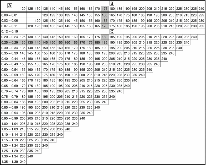
-
Measured clearance
-
Installed pad number
-
Standard clearance
Example:
Valve clearance (cold) 0.12–0.19 mm (0.0047–0.0075 in)
Installed is 175.
Measured clearance 0.27 mm (0.0106 in)
Replace 175 pad with 185 pad.
Pad No. 175 = 1.75 mm (0.0689 in)
Pad No. 185 = 1.85 mm (0.0728 in)
EXHAUST
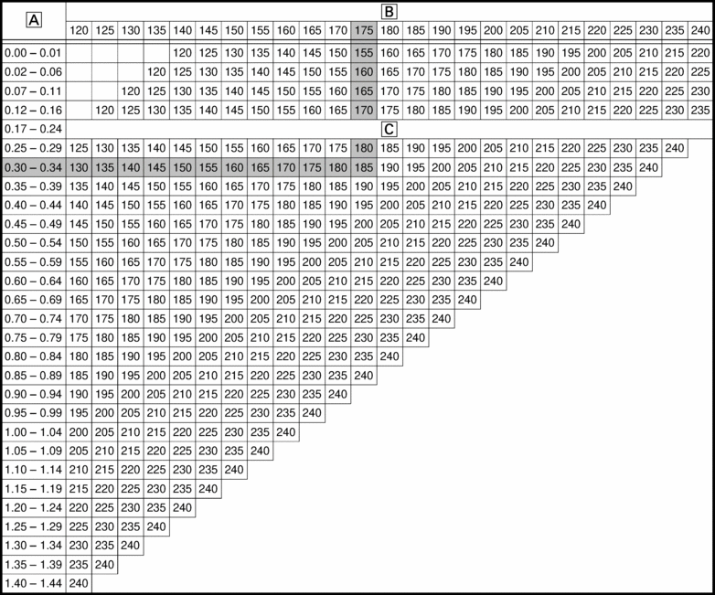
-
Measured clearance
-
Installed pad number
-
Standard clearance
Example:
Valve clearance (cold) 0.17–0.24 mm (0.0067–0.0094 in)
Installed is 175.
Measured clearance 0.32 mm (0.0126 in)
Replace 175 pad with 185 pad.
Pad No. 175 = 1.75 mm (0.0689 in)
Pad No. 185 = 1.85 mm (0.0728 in)
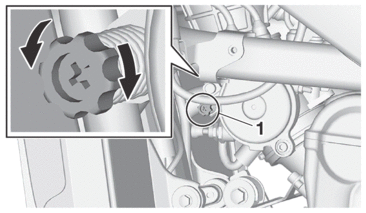
CHECKING THE ENGINE IDLING SPEED
|
1.Start the engine, and warm this up until the oil has reached the specified temperature.
2.Measure the coolant temperature using the Yamaha diagnostic tool.
|
|
3.Install:
-
Digital tachometer
|
|
4.Measure:
-
Engine idling speed
Out of specification → Regulate.
|

5.Adjust:
-
Engine idling speed
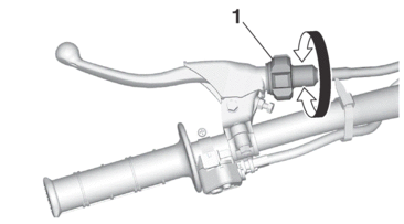
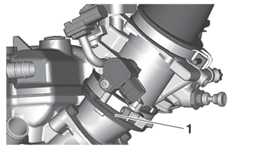
a.Turn the idle screw “1” to make an adjustment.
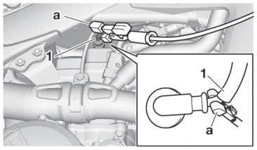
CHECKING THE THROTTLE GRIP
|
1.Check:
-
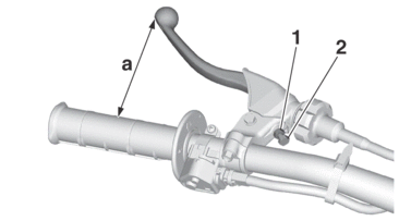
Throttle grip free play “a”
Out of specification → Regulate.
|
2.Adjust:
-
Throttle grip free play
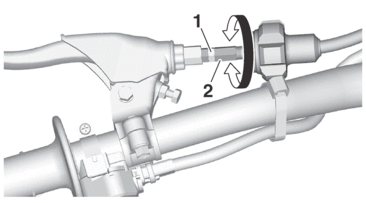
a.Loosen the locknut “1”.
b.Turn the adjuster “2” until the specified throttle grip free play is obtained.
c.Tighten the locknut.
|

CHECKING THE SPARK PLUG
1.Remove:
-
Seat
-
Side cover (left/right)
-
Shroud (left/right)
Refer to GENERAL CHASSIS.
-
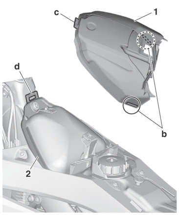
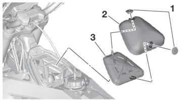
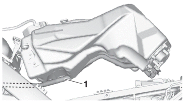
Fuel tank “1”
Refer to FUEL TANK.
|
|
2.Remove:
-
Holder
-
Spark plug cap
-
Spark plug
Refer to CAMSHAFT.
|
3.Check:
-
Spark plug type
Wrong type → Replace.
|
4.Check:
-
Electrode “1”
Damage/wear → Replace the spark plug.
-
Insulator “2”
Abnormal color → Replace the spark plug.
Normal color is medium-to-light tan.
5.Clean:
-
Spark plug
(with a spark plug cleaner or a wire brush)
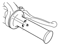
6.Measure:
-
Spark plug gap “a”
Out of specification → Adjust the spark plug gap.
|
7.Install:
-
Spark plug
|

|
8.Install:
-
Spark plug cap
-
Holder
-
Fuel tank
Refer to FUEL TANK.
-
Shroud (left/right)
-
Side cover (left/right)
-
Seat
Refer to GENERAL CHASSIS.
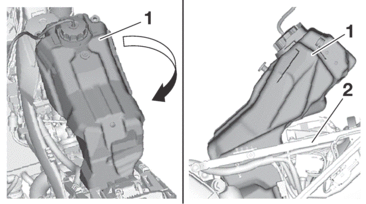
CHECKING THE ENGINE OIL LEVEL
1.Stand the vehicle upright on a level surface.
2.Start the engine, warm this up for 2–3 minutes, and then stop the engine and wait about 1 minute.
3.Check:
-
Oil level
The engine oil level should be between the minimum level mark “a” and maximum level mark “b”.
Below the minimum level mark → Add the recommended engine oil to the proper level.
|
|


CHANGING THE ENGINE OIL
Stand the vehicle upright on a level surface.
1.Start the engine, warm this up for several minutes, and then stop the engine and wait about 5 minutes.
|
2.Place an oil pan under the drain bolt.
4.If the oil filter element is also to be replaced, perform the following procedure.
a.Remove the oil filter element cover “1” and oil filter element “2”.
b.Replace the new O-ring “3”.
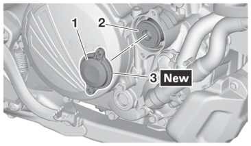
c.Install the new oil filter element and the oil filter element cover.
|
5.To check the oil strainer, perform the following procedure.
a.Remove the oil strainer “1”.
b.Check the oil strainer.
Damage → Replace.
Clogging due to dirt → Wash with kerosene.
c.Replace the new O-ring “2”.
d.Install the oil strainer.
|

6.Install:
-
Gasket

-
Drain bolt
|
7.Pour the specified amount of engine oil into the oil filler cap hole.
|
8.Install:
-
Oil filler cap
9.Check:
-
Oil level
Refer to CHECKING THE ENGINE OIL LEVEL.
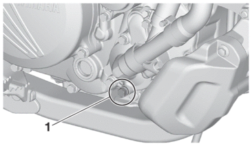
10.Check:
-
Engine oil pressure
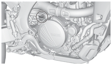
a.Slightly loosen the oil pressure check bolt “1”.
|
b.Start the engine and keep it idling until oil starts to seep from the oil pressure check bolt.
|
|
c.If no engine oil seeps out, check the engine oil for leaks, and the engine oil passage and the oil pump for damage.
d.Check the oil pressure again.
e.Tighten the oil pressure check bolt.
|
11.Install:
-
Engine guard
Refer to ENGINE REMOVAL.
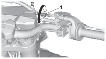
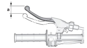
ADJUSTING THE CLUTCH LEVER FREE PLAY
1.Check:
-
Clutch lever free play “a”
Out of specification → Regulate.
|
2.Adjust:
-
Clutch lever free play
Handlebar side
a.Turn the adjuster “1” until the specified clutch lever free play is obtained.
|
Clutch cable side
a.Slide the clutch cable cover.
b.Loosen the locknut “1”.
c.Turn the adjuster “2” until the specified clutch lever free play is obtained.
d.Tighten the locknut “1”.
|
e.Return the clutch cable cover to its original position.
ADJUSTING THE CLUTCH LEVER POSITION
1.Adjust:
-
Clutch lever position “a”
Loosen the locknut “1” and use the adjuster “2” to adjust the clutch lever position “a” as desired.
2.Tighten:
-
Locknut
|
CLEANING THE AIR FILTER ELEMENT
1.Remove:
-
Sub-seat
Refer to FUEL TANK CAP.
-
Air filter case cover “1”
|
2.Remove:
-
Air filter element guide “1”
-
Air filter element “2”
(from the air filter element guide)
-
Seal “3”
(from the air filter element)
|
3.Wash:
-
Air filter element
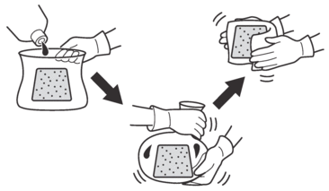
a.After washing the element with air filter cleaner or kerosene, squeeze and dry it completely.
|
|
4.Check:
-
Air filter element
Damage → Replace.
5.Apply:
-
Yamaha foam air filter oil or other quality foam air filter oil
a.Put the air filter element into a plastic bag and drip the filter oil into the bag.
b.With the element inside the bag, rub it thoroughly so that the element is evenly permeated with the oil.
c.Wrap the element in a clean cloth, rub the element gently, and wipe off any excess oil.
|
6.Install:
-
Air filter case assembly bracket
(if removed)
Refer to THROTTLE BODY.
-
Seal “1”
(to the air filter element)
-
Air filter element “2”
(to the air filter element guide)
-
Air filter element guide “3”
|
7.Install:
-
Air filter case cover “1”
-
Fuel tank breather hose “2”
(to the air filter case cover)
|
8.Install:
-
Sub-seat
CHECKING THE THROTTLE BODY JOINT
1.Check:
-
Throttle body joint “1”
Crack/damage → Replace.
CHECKING THE FUEL LINE
1.Remove:
-
Seat
-
Side cover (left/right)
-
Shroud (left/right)
Refer to GENERAL CHASSIS.
-
Fuel tank
Refer to FUEL TANK.
2.Check:
-
Fuel hose “1”
Crack/damage → Replace.
Loose connection → Connect properly.
3.Install:
-
Fuel tank
Refer to FUEL TANK.
-
Shroud (left/right)
-
Side cover (left/right)
-
Seat
Refer to GENERAL CHASSIS.
CHECKING THE CYLINDER HEAD BREATHER HOSE
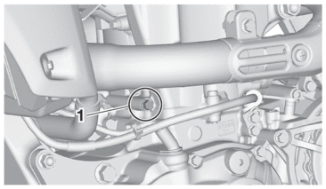
1.Check:
-
Breather hose “1”
Crack/damage → Replace.
Loose connection → Connect properly.
|
CHECKING THE EXHAUST SYSTEM
|
1.Remove:
-
Exhaust pipe 1
-
Exhaust pipe 2
Refer to ENGINE REMOVAL.
2.Remove:
-
Exhaust pipe protector
3.Check:
-
Exhaust pipe 1
-
Exhaust pipe 2
-
Silencer
Crack/damage → Replace.
Refer to ENGINE REMOVAL.
4.Check:
-
Spark arrester
Carbon deposits → clean
5.Clean:
-
Spark arrester
a.Remove the silencer cap screws “1”.
b.Remove the spark arrester bolts “2”.
c.Remove the tail pipe “3”, tail pipe gasket “4” and spark arrester “5”.
|
d.Remove the spark arrester gasket “6”.
e.Clean the spark arrester.
|
f.Install the spark arrester gasket (new gasket) and spark arrester.
|
g.Install the tail pipe gasket (new gasket) and spark arrester bolts.
|
h.Install the silencer cap.
|
|
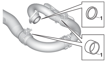
6.Check:
-
Gasket “1”
Damage → Replace.
7.Install:
-
Exhaust pipe 1
-
Exhaust pipe 2
Refer to INSTALLING THE EXHAUST PIPE AND MUFFLER.
8.Install:
-
Exhaust pipe protector
|
CHECKING THE COOLANT LEVEL
|
1.Stand the vehicle upright on a level surface.
2.Remove:
-
Radiator cap “1”
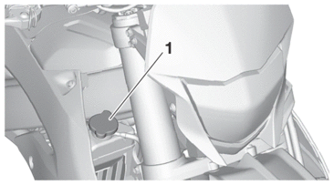
3.Check:
-
Coolant level
Maximum level “a” or below → Add coolant up to the maximum level.
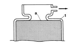
1.
Radiator
|
4.Start the engine, warm this up for several minutes, and then stop it.
5.Check:
-
Coolant level
|
CHECKING THE COOLING SYSTEM
1.Remove:
-
Seat
-
Side cover (left/right)
-
Shroud (left/right)
Refer to GENERAL CHASSIS.
2.Check:
-
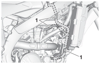
Radiator
-
Radiator hose
Crack/damage → Replace.
Refer to RADIATOR.
3.Install:
-
Shroud (left/right)
-
Side cover (left/right)
-
Seat
Refer to GENERAL CHASSIS.
CHANGING THE COOLANT
|
1.Place a container under the engine.
3.Remove:
-
Radiator cap
Slowly loosen the radiator cap to drain coolant.

-
When the radiator cap is loosened, coolant will gush out transversely; therefore, bring the container near to the outlet.
4.Thoroughly flush the cooling system with clean tap water.
5.Install:
-
Copper washer
-
Coolant drain bolt
|
6.Pour coolant.
|
|
|
7.Install:
-
Radiator cap
8.Start the engine, warm this up for several minutes, stop it, and then wait for it to cool down.
9.Check:
-
Coolant level
Refer to CHECKING THE COOLANT LEVEL.
10.Install:
-
Engine guard
Refer to ENGINE REMOVAL.